6 M -6 CARBURETORS
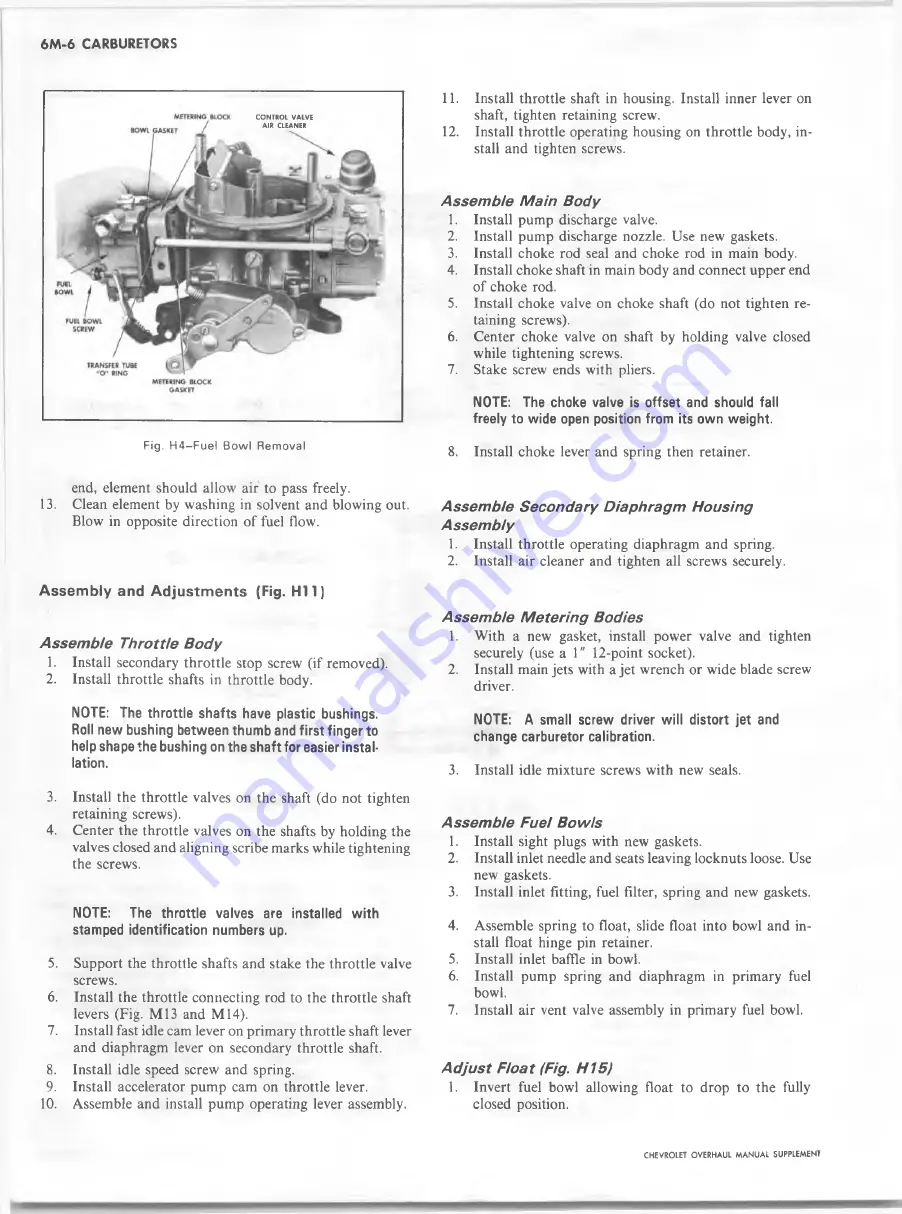
CONTROL VALVE
AIR CLEANER
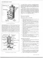
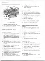
Fig. H4~Fuel Bow l Removal
end, element should allow air to pass freely.
13. Clean element by washing in solvent and blowing out.
Blow in opposite direction of fuel flow.
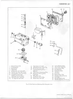
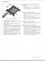
A s s e m b ly and A d ju stm e n ts (Fig. H I 1)
A sse m b le Throttle Bod y
1.
Install secondary throttle stop screw (if removed).
2. Install throttle shafts in throttle body.
NOTE: The throttle shafts have plastic bushings.
Roll new bushing between thumb and firs t finger to
help shape the bushing on the shaft for easier instal
lation.
3. Install the throttle valves on the shaft (do not tighten
retaining screws).
4. Center the throttle valves on the shafts by holding the
valves closed and aligning scribe marks while tightening
the screws.
NOTE:
The throttle valves are installed w ith
stamped identification numbers up.
5.
Support the throttle shafts and stake the throttle valve
screws.
6
.
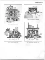
Install the throttle connecting rod to the throttle shaft
levers (Fig. M13 and M14).
7.
Install fast idle cam lever on primary throttle shaft lever
and diaphragm lever on secondary throttle shaft.
8
.
Install idle speed screw and spring.
9.
Install accelerator pump cam on throttle lever.
10. Assemble and install pump operating lever assembly.
11. Install throttle shaft in housing. Install inner lever on
shaft, tighten retaining screw.
12.
Install throttle operating housing on throttle body, in
stall and tighten screws.
A sse m b le M ain Body
1.
Install pump discharge valve.
2.
Install pump discharge nozzle. Use new gaskets.
3.
Install choke rod seal and choke rod in main body.
4. Install choke shaft in main body and connect upper end
of choke rod.
5. Install choke valve on choke shaft (do not tighten re
taining screws).
6
. Center choke valve on shaft by holding valve closed
while tightening screws.
7. Stake screw ends with pliers.
NOTE: The choke valve is offset and should fall
freely to wide open position from its own weight.
8
.
Install choke lever and spring then retainer.
A sse m b le Secondary Diaphragm H ousing
A sse m b ly
1. Install throttle operating diaphragm and spring.
2. Install air cleaner and tighten all screws securely.
A ssem ble M etering Bodies
1. With a new gasket, install power valve and tighten
securely (use a
1
"
1 2
-point socket).
2. Install main jets with a jet wrench or wide blade screw
driver.
NOTE: A small screw driver w ill distort jet and
change carburetor calibration.
3.
Install idle mixture screws with new seals.
A sse m b le Fuel Bow ls
1.
Install sight plugs with new gaskets.
2.
Install inlet needle and seats leaving locknuts loose. Use
new gaskets.
3.
Install inlet fitting, fuel filter, spring and new gaskets.
4. Assemble spring to float, slide float into bowl and in
stall float hinge pin retainer.
5.
Install inlet baffle in bowl.
6
.
Install pump spring and diaphragm in primary fuel
bowl.
7.
Install air vent valve assembly in primary fuel bowl.
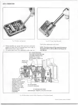
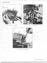
A d ju st Float (Fig. H15)
1. Invert fuel bowl allowing float to drop to the fully
closed position.
CHEVROLET OVERHAUL M A N U A L SUPPLEMENT
Summary of Contents for 40 60 Series
Page 1: ...40 60 SERIES TRUCK SUPPLEMENT ST 334 72...
Page 86: ......
Page 96: ...n 47 k u m i i i iin I ll II I...
Page 222: ......

