DELCOTRON 6Y-7
6
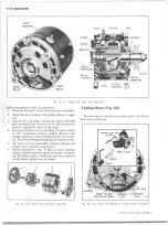
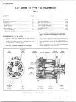
. Disconnect the slip ring end frame from the 3 external
terminals and separate the end frame from the rear of
the stator shell.
NOTE: A t this point, the generator is disassembled
sufficiently to allow the subsequent cleaning, in
spection, testing and replacement operations ou
tlined in this section.
C LE A N IN G A N D IN SP E C T IO N
With generator completely disassembled, except for re
moval of diodes, the components should be cleaned and in
spected. Be sure testing equipment is in good working order
before attempting to check the generator.
1. Wash all metal parts except stator and rotor assemblies.
2. Clean bearings and inspect for sealing, pitting or rough
ness.
3. Inspect rotor slip rings, they may be cleaned with 400
grain polishing cloth. Rotate rotor for this operation to
prevent creating flat spots on slip rings.
4. Slip rings which are out of round may be trued in a lathe
to .001" rings smooth and concentric. Finish with 400
grain polishing cloth and blow dry.
5. Slip rings are not replaceable—excessive damage will
require rotor assembly replacement.
6
. Inspect brushes for wear. If they are worn halfway,
replace. Inspect brush springs for distortion or weaken
ing. If brushes appear satisfactory and move freely in
brush holder, springs may be reused.
TESTIN G ROTOR
The rotor may be checked electrically with a 110-volt test
lamp or an ohmmeter.
Grounds
Connect test lamp or ohmmeter from either slip ring to
the rotor shaft or to the rotor poles. If the lamp lights or if
the ohmmeter reading is low, the field windings are
grounded.
Open Circuit
Connect one test lamp or ohmmeter lead to each slip ring.
If the lamp fails to light or if the ohmmeter reading is high,
the windings are open.
Short Circuit
The windings are checked for shorts by connecting a 12
volt battery and an ammeter in series with the two slip rings.
Note the ammeter reading. An ammeter reading above the
specified field amperage draw indicates shorted windings.
Refer to Specifications or appropriate service bulletin.
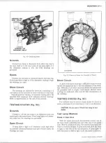
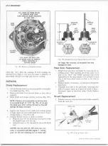
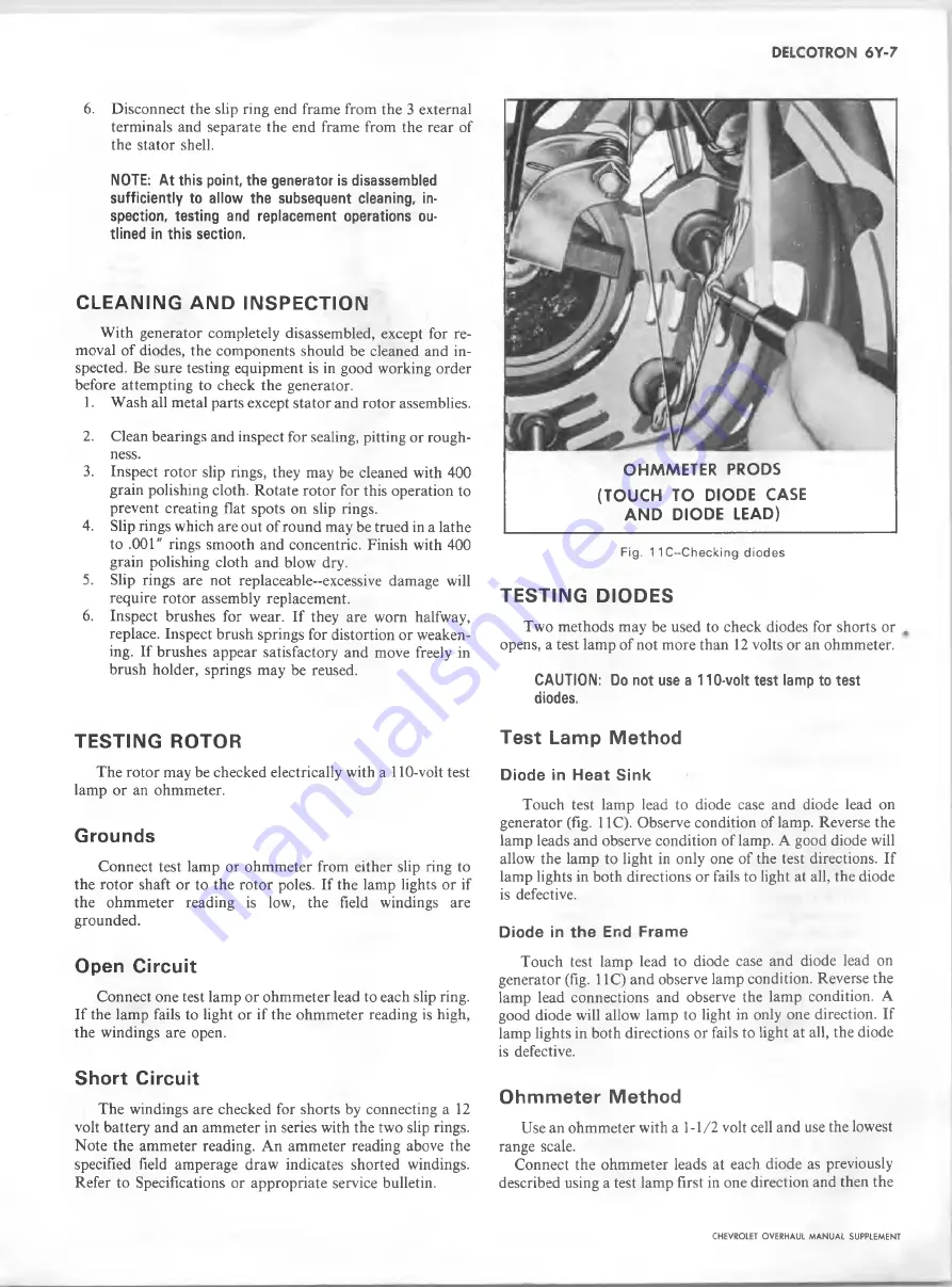
O H M M E T E R P R O D S
(T O U C H TO D IO D E C A S E
A N D D IO D E LEAD)
Fig. 1 1 C~Checking diodes
TESTIN G D IO D E S
Two methods may be used to check diodes for shorts or ,
opens, a test lamp of not more than
1 2
volts or an ohmmeter.
CAUTION: Do not use a 110-volt test lamp to test
diodes.
Test Lamp Method
D iode in H e a t S in k
Touch test lamp lead to diode case and diode lead on
generator (fig. 11C). Observe condition of lamp. Reverse the
lamp leads and observe condition of lamp. A good diode will
allow the lamp to light in only one of the test directions. If
lamp lights in both directions or fails to light at all, the diode
is defective.
Diode in the End Fram e
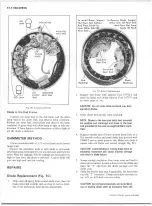
Touch test lamp lead to diode case and diode lead on
generator (fig. 11C) and observe lamp condition. Reverse the
lamp lead connections and observe the lamp condition. A
good diode will allow lamp to light in only one direction. If
lamp lights in both directions or fails to light at all, the diode
is defective.
Ohmmeter Method
Use an ohmmeter with a 1-1/2 volt cell and use the lowest
range scale.
Connect the ohmmeter leads at each diode as previously
described using a test lamp first in one direction and then the
CHEVROLET OVERHAUL M A N U A L SUPPLEMENT
Summary of Contents for 40 60 Series
Page 1: ...40 60 SERIES TRUCK SUPPLEMENT ST 334 72...
Page 86: ......
Page 96: ...n 47 k u m i i i iin I ll II I...
Page 222: ......


