6Y-8 DELCOTRON
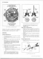
C U T L E A D S A T T H R E E P L A C E S
T O R E M O V E H E A T S I N K ,
T H E N R E P L A C E D I O D E M O U N T E D
I N H E A T S I N K
H E A T
S I N K
O U T S I D E ^
F R A M E
C U T L E A D S O N E A C H S I D E
O F D I O D E L E A D T O R E M O V E
D I O D E M O U N T E D I N
O U T S I D E F R A M E
P O S I T I V E
L E A D
RIG HT
H A N D
T H R E A D S
N E G A T I V E
C A S E
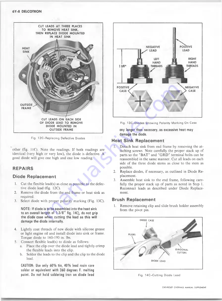
Fig. 1 2C~Replacing Defective Diodes
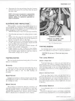
other (fig. 11C). Note the readings. If both readings are
identical (very high or very low), the diode is defective. A
good diode will give one high and one low reading.
R E P A IR S
Diode Replacement
1. Cut the flexible lead(s) as close as possible to the defec
tive diode lead (fig. 12C).
2. Remove the diode from the end frame or heat sink as
required.
3. Select diode with proper polarity marking (Fig. 13C).
NOTE: If diode is to be assembled into the heat sink
to an overall length of 1-3/8" fig. 14C), do not grip
the diode case when cutting the lead as this will
damage the diode internally.
4. Lightly coat threads of new diode with silicone grease
or light engine oil and install diode into sink or frame.
Torque diode to 160-190 in. lbs.
5. Connect flexible lead(s) to diode as follows:
a.
Place the clip over the diode lead and tightly crimp
the flexible leads into the clip.
b.
Solder the leads to the clip and the clip to the diode
lead.
CAUTION: Use only 60% tin, 40% lead rosin core
solder or equivalent with 360 degrees F. melting
point. Do not hold soldering iron on diode lead
Fig. 13C~Diodes Show ing P olarity M arking On Case
any longer than necessary, as excessive heat may
damage the diode.
Heat Sink Replacement
1. Detach heat sink from end frame by removing the at
taching screws. Note carefully the proper stack up of
parts so the "BAT" and "GRD " terminal bolts can be
reassembled in the same manner. Cut all leads on each
side of the three diode stems as close to the stem as
possible.
2.
Replace diodes, if necessary, as outlined in Diode Re
placement.
3. Assemble heat sink to the end frame, following care
fully the proper stack up of parts as noted in Step 1.
Reconnect leads as described under Diode Replace
ment.
Brush Replacement
1. Remove retaining clip and slide brush holder assembly
from the pivot pin.
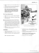
Fig. 14C--Cutting Diode Lead
CHEVROLET OVERHAUL M A N U A L SUPPLEMENT
d io d e
case
I
PLIERS
d ia g o n a l
CUTTERS
DIODE LEAD
Summary of Contents for 40 60 Series
Page 1: ...40 60 SERIES TRUCK SUPPLEMENT ST 334 72...
Page 86: ......
Page 96: ...n 47 k u m i i i iin I ll II I...
Page 222: ......

