T R A N SM ISSIO N A N D CLUTCH 7-15
foreign material has been removed.
2.
Rinse bearings in clean solvent; then blow bearings dry
with air pressure. DO NOT SPIN BEARINGS
W HILE DRYING.
3.
Rotate bearing slowly while examining balls or rollers
for roughness, damage, or excessive wear. Replace all
bearings which are in questionable condition.
4.
Pack all bearings with bearing lubricant (such as NLGI
No. 0 Light Weight Ball and Roller Bearing Grease or
equivalent).
5. Wrap each bearing in clean lint-free paper until ready
to install in transmission.
Gears and Shafts
1.
Check operating gear teeth for pitting on tooth faces.
Gears with pitted teeth should be replaced.
2.
Check all engaging gear teeth. Gears with teeth worn,
tapered or reduced in length from clashing in shifting
should be replaced.
NOTE: Small nicks or burrs may be removed w ith a
fine abrasive stone.
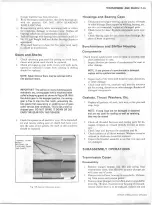
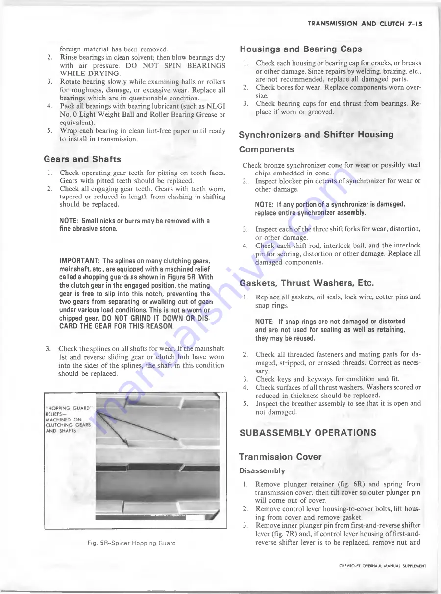
IMPORTANT: The splines on many clutching gears,
mainshaft, etc., are equipped w ith a machined relief
called a ihopping guardi as shown in Figure 5R. W ith
the clutch gear in the engaged position, the mating
gear is free to slip into this notch, preventing the
tw o gears from separating or iwalking out of gean
under various load conditions. This is not a worn or
chipped gear. DO NOT GRIND IT DOWN OR DIS
CARD THE GEAR FOR THIS REASON.
3. Check the splines on all shafts for wear. If the mainshaft
1
st and reverse sliding gear or clutch hub have worn
into the sides of the splines, the shaft in this condition
should be replaced.
Fig. 5R ~Spicer Hopping Guard
Housings and Bearing Caps
1. Check each housing or bearing cap for cracks, or breaks
or other damage. Since repairs by welding, brazing, etc.,
are not recommended, replace all damaged parts.
2. Check bores for wear. Replace components worn over
size.
3.
Check bearing caps for end thrust from bearings. Re
place if worn or grooved.
Synchronizers and Shifter Housing
Components
Check bronze synchronizer cone for wear or possibly steel
chips embedded in cone.
2.
Inspect blocker pin detents of synchronizer for wear or
other damage.
NOTE: If any portion of a synchronizer is damaged,
replace entire synchronizer assembly.
3. Inspect each of the three shift forks for wear, distortion,
or other damage.
4. Check each shift rod, interlock ball, and the interlock
pin for scoring, distortion or other damage. Replace all
damaged components.
Gaskets, Thrust Washers, Etc.
1.
Replace all gaskets, oil seals, lock wire, cotter pins and
snap rings.
NOTE: If snap rings are not damaged or distorted
and are not used for sealing as well as retaining,
they may be reused.
2. Check all threaded fasteners and mating parts for da
maged, stripped, or crossed threads. Correct as neces
sary.
3. Check keys and keyways for condition and fit.
4. Check surfaces of all thrust washers. Washers scored or
reduced in thickness should be replaced.
5.
Inspect the breather assembly to see that it is open and
not damaged.
S U B A S S E M B L Y O P E R A T IO N S
Tranmission Cover
D is a ss e m b ly
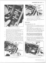
1.
Remove plunger retainer (fig.
6
R) and spring from
transmission cover, then tilt cover so outer plunger pin
will come out of cover.
2. Remove control lever housing-to-cover bolts, lift hous
ing from cover and remove gasket.
3. Remove inner plunger pin from first-and-reverse shifter
lever (fig. 7R) and, if control lever housing of first-and-
reverse shifter lever is to be replaced, remove nut and
CHEVROLET OVERHAUL M A N U A L SUPPLEMENT
Summary of Contents for 40 60 Series
Page 1: ...40 60 SERIES TRUCK SUPPLEMENT ST 334 72...
Page 86: ......
Page 96: ...n 47 k u m i i i iin I ll II I...
Page 222: ......

