REAR AXLE DIFFERENTIAL CARRIER 4-17
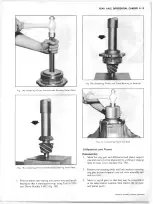
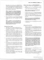
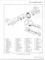
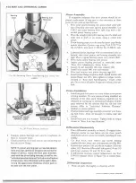
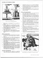
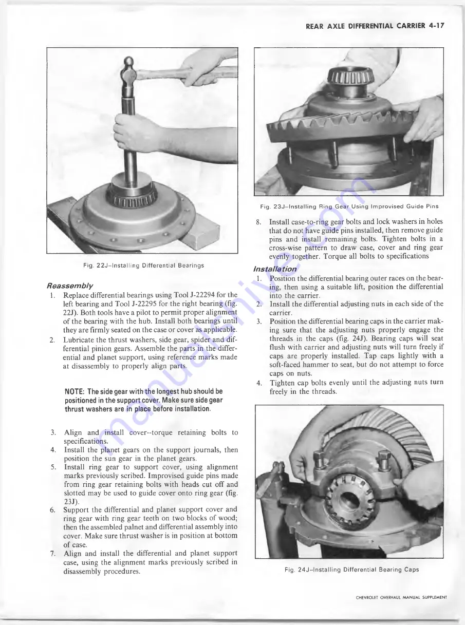
Fig. 2 2 J — InstaIIing D iffe re n tia l Bearings
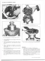
F ig . 2 3 J - - ln s t a llin g R in g G e a r U s in g Im p r o v is e d G u id e P in s
Reassem bly
1. Replace differential bearings using Tool J-22294 for the
left bearing and Tool J-22295 for the right bearing (fig.
22J). Both tools have a pilot to permit proper alignment
of the bearing with the hub. Install both bearings until
they are firmly seated on the case or cover as applicable.
2.
Lubricate the thrust washers, side gear, spider and dif
ferential pinion gears. Assemble the parts in the differ
ential and planet support, using reference marks made
at disassembly to properly align parts.
NOTE: The side gear w ith the longest hub should be
positioned in the support cover. Make sure side gear
thrust washers are in place before installation.
3.
Align and install cover-torque retaining bolts to
specifications.
4.
Install the planet gears on the support journals, then
position the sun gear in the planet gears.
5.
Install ring gear to support cover, using alignment
marks previously scribed. Improvised guide pins made
from ring gear retaining bolts with heads cut off and
slotted may be used to guide cover onto ring gear (fig.
23J).
6
. Support the differential and planet support cover and
ring gear with ring gear teeth on two blocks of wood;
then the assembled palnet and differential assembly into
cover. Make sure thrust washer is in position at bottom
of case.
7.
Align and install the differential and planet support
case, using the alignment marks previously scribed in
disassembly procedures.
8
. Install case-to-ring gear bolts and lock washers in holes
that do not have guide pins installed, then remove guide
pins and install remaining bolts. Tighten bolts in a
cross-wise pattern to draw case, cover and ring gear
evenly together. Torque all bolts to specifications
Installation
1.
Position the differential bearing outer races on the bear
ing, then using a suitable lift, position the differential
into the carrier.
2.
Install the differential adjusting nuts in each side of the
carrier.
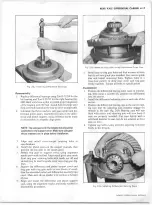
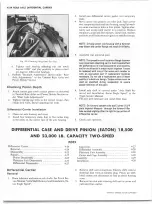
3. Position the differential bearing caps in the carrier mak
ing sure that the adjusting nuts properly engage the
threads in the caps (fig. 24J). Bearing caps will seat
flush with carrier and adjusting nuts will turn freely if
caps are properly installed. Tap caps lightly with a
soft-faced hammer to seat, but do not attempt to force
caps on nuts.
4. Tighten cap bolts evenly until the adjusting nuts turn
freely in the threads.
Fig. 2 4 J — Installing D iffere ntial Bearing Caps
CHEVROLET OVERHAUL M A N U A L SUPPLEMENT
Summary of Contents for 40 60 Series
Page 1: ...40 60 SERIES TRUCK SUPPLEMENT ST 334 72...
Page 86: ......
Page 96: ...n 47 k u m i i i iin I ll II I...
Page 222: ......


