4-20 REAR AXLE DIFFERENTIAL CARRIER
DIFFERENTIAL CASE A N D DRIVE P IN IO N (EATON) 18,500
A N D 23,000 LB. CAPACITY SINGLE-SPEED
INDEX
Differential Carrier Assembly ....................................... 4-20
Removal.......................................................................... 4-20
Disassembly................................................................ ... 4-20
Repairs......................................................................... ... 4-20
Pinion Disassembly.................................................. 4-20
Pinion Installation................................................. ... 4-22
Differential Disassembly...................................... .......4-22
Differential Inspection.......................................... .......4-22
Differential Reassembly ...................................... .......4-23
Reassembly ................................................................ .......4-23
Installation................................................................ .......4-24
DIFFERENTIAL C A R R IE R A S S E M B L Y
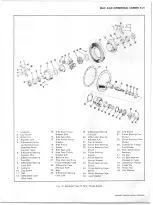
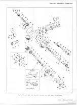
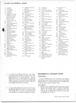
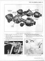
(Refer to Figure 1 K)
R e m o val
1. Drain lubricant from differential, and remove axle
shafts. See Truck Service Manual, "Axle Shaft Removal
and Installation, Eaton Single Speed."
2. Remove two trunnion bearing "U" bolts from the pin
ion flange and split the rear universal joint.
NOTE: The bearings can be le ft on the trunnion and
held in place w ith tape.
3. Swing propeller shaft to one side and tie it to the frame
side rail.
4. Remove all differential carrier to axle housing bolts and
lock washers, except the two near top. Loosen two at
top and leave installed to prevent carrier from falling.
5. Break carrier loose from axle housing by tapping carrier
with rawhide mallet.
6
. Support carrier on roller jack; then remove the two top
bolts and lock washers. A small pinch bar may be used
to keep carrier straight in housing bore while carrier is
withdrawn, provided end of bar is rounded to prevent
damage to carrier flange.
D is a ss e m b ly
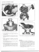
1. Mount differential carrier in Holding Fixture J-3409 or
in a vise equipped with padded jaws. Key numbers in
text refer to Figure IK unless otherwise noted.
2. Center punch side of differential carrier leg and bearing
cap, for identification when reassembling.
3.
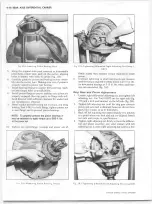
Remove bearing cap attaching bolts, bearing caps (5),
and adjusters (
6
) and (26).
4.
Lift differential and gear assembly from carrier.
CAUTION: Exercise care th at differential side bear
ing cups (7) are not dropped in removing assembly
from housing.
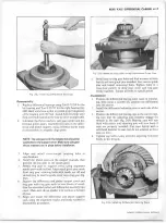
5. Remove bolts and lock washers which attach pinion
cage (34) to carrier. Invert carrier and tap inner end of
drive pinion until pinion and cage assembly drops free
of carrier.
6
. Remove adjusting shims (33) from between carrier and
cage. Wire shim pack together to maintain bolt hole
alignment at reassembly.
R ep airs
Pinion Disassem bly
1.
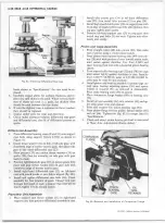
Place companion flange in vise, remove cotter pin, nut
and flange washer (fig.
6
L).
2. Place assembly in arbor press with cage on bed of arbor.
Press drive pinion (21) downward and out of cage.
3.
Remove pinion flange, and retainer and oil seal assem
bly (42). Remove pinion bearing spacer (30), from pin
ion.
4. Lift outer bearing cone and roller assembly (38) from
cage.
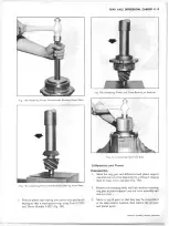
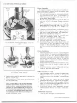
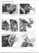
5. When inspection indicates necessity, cups (32 and 37)
can be removed from cage with Tool J-3940 as shown
in Figure 2K.
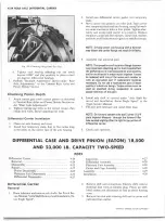
6
. Remove stake points holding straight roller bearing
(28) to pinion, then press pinion from bearing with
bearing supported by Tool J-3493 as shown in Figure
3K.
7. Remove inner pinion cone (29). Position Tool J-3493
over head of pinion so that it contacts inner race and
press pinion from bearing (fig. 3K).
Pinion Inspection
1. Wash all parts thoroughly in cleaning solvent.
2.
Inspect splines of pinion shaft for excessive wear.
3.
Inspect pinion for scored, cracked, chipped or worn
teeth.
CHEVROLET OVERHAUL M A N U A L SUPPLEMENT
Summary of Contents for 40 60 Series
Page 1: ...40 60 SERIES TRUCK SUPPLEMENT ST 334 72...
Page 86: ......
Page 96: ...n 47 k u m i i i iin I ll II I...
Page 222: ......


