4-24 REAR AXLE DIFFERENTIAL CARRIER
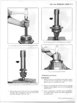
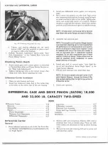
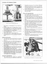
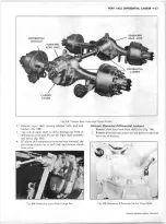
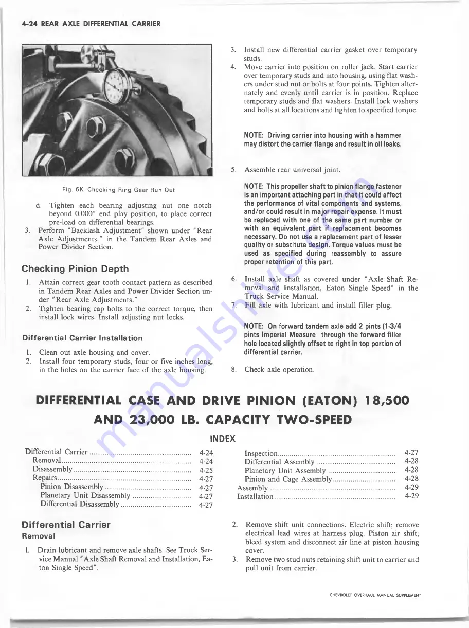
Fig. 6K--C hecking Ring Gear Run Out
d. Tighten each bearing adjusting nut one notch
beyond
0
.
0 0 0
" end play position, to place correct
pre-load on differential bearings.
3. Perform "Backlash Adjustment" shown under "Rear
Axle Adjustments." in the Tandem Rear Axles and
Power Divider Section.
Checking Pinion Depth
1. Attain correct gear tooth contact pattern as described
in Tandem Rear Axles and Power Divider Section un
der "Rear Axle Adjustments."
2. Tighten bearing cap bolts to the correct torque, then
install lock wires. Install adjusting nut locks.
D iffe rential Carrier In sta lla tio n
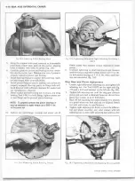
1. Clean out axle housing and cover.
2. Install four temporary studs, four or five inches long,
in the holes on the carrier face of the axle housing.
3. Install new differential carrier gasket over temporary
studs.
4.
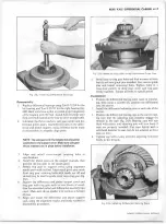
Move carrier into position on roller jack. Start carrier
over temporary studs and into housing, using flat wash
ers under stud nut or bolts at four points. Tighten alter
nately and evenly until carrier is in position. Replace
temporary studs and flat washers. Install lock washers
and bolts at all locations and tighten to specified torque.
NOTE: Driving carrier into housing w ith a hammer
may distort the carrier flange and result in oil leaks.
5. Assemble rear universal joint.
NOTE: This propeller shaft to pinion flange fastener
is an important attaching part in th at it could affect
the performance of vital components and systems,
and/or could result in major repair expense. It must
be replaced w ith one of the same part number or
w ith an equivalent part if replacement becomes
necessary. Do not use a replacement part of lesser
quality or substitute design. Torque values must be
used as specified during reassembly to assure
proper retention of this part.
6
.
Install axle shaft as covered under "Axle Shaft Re
moval and Installation, Eaton Single Speed" in the
Truck Service Manual.
7. Fill axle with lubricant and install filler plug.
NOTE: On forward tandem axle add 2 pints (1-3/4
pints Imperial Measure through the forw ard filler
hole located slightly offset to right in top portion of
differential carrier.
8
. Check axle operation.
DIFFERENTIAL CASE A N D DRIVE P IN IO N (EATON) 18,500
A N D 23,000 LB. CAPACITY TWO-SPEED
INDEX
Differential C a rrie r....................................................... ... 4-24
Removal.......................................................................... 4-24
Disassembly................................................................ ... 4-25
R epairs............................................................................ 4-27
Pinion Disassembly.................................................. 4-27
Planetary Unit Disassembly............................... ... 4-27
Differential Disassembly......................................... 4-27
Inspection................................................................
Differential A ssem bly..........................................
Planetary Unit Assembly ....................................
Pinion and Cage Assembly..................................
A ssem bly....................................................................
Installation..................................................................
Differential Carrier
2
.
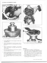
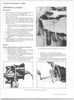
R em o val
1. Drain lubricant and remove axle shafts. See Truck Ser
vice Manual "Axle Shaft Removal and Installation, Ea-
3.
ton Single Speed".
Remove shift unit connections. Electric shift; remove
electrical lead wires at harness plug. Piston air shift;
bleed system and disconnect air line at piston housing
cover.
Remove two stud nuts retaining shift unit to carrier and
pull unit from carrier.
CHEVROLET OVERHAUL M A N U A L SUPPLEMENT
Summary of Contents for 40 60 Series
Page 1: ...40 60 SERIES TRUCK SUPPLEMENT ST 334 72...
Page 86: ......
Page 96: ...n 47 k u m i i i iin I ll II I...
Page 222: ......


