4-30 REAR AXLE DIFFERENTIAL CARRIER
4. Install shift fork seal (44) and spring (45) over shift
fork. Be sure that hole in seal marked "BOTTOM
HOLE" is at bottom.
In sta llatio n
1. Clean out axle housing and cover.
2. Install four temporary studs, four or five inches long in
the holes on the carrier face of the axle housing.
3. Install new differential carrier gasket over temporary
studs.
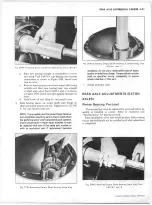
4. Move carrier into position on roller jack. Start carrier
over temporary studs and into housing, using flat wash
ers under stud nut or bolts at four points. Tighten alter
nately and evenly until carrier is in position. Replace
temporary studs and flat washers. Install lock washers
and bolts at all locations and tighten to specified torque.
NOTE: Driving carrier into housing w ith a hammer
may distort the carrier flange and result in oil leaks.
5. Install shaft unit and connect lead wires to harness plug
or air line to piston housing cover on Piston-Air units.
6
. Assemble rear universal joint.
NOTE: This propeller shaft to pinion flange fastener
is an important attaching part in that it could affect
the performance of vital components and systems,
and/or could result in major repair expense. It must
be replaced w ith one of the same part number or
w ith an equivalent part if replacement becomes
necessary. Do not use a replacement part of lesser
quality or substitute design. Torque values must be
used as specified during reassembly to assure
proper retention of this part.
7.
Install axle shafts as covered under "Axle Shaft Re
moval and Installation" in the Truck Service Manual,
Eaton Single Speed.
8
. Fill axle with recommended gear lubricant, and install
filler plug.
9. Check axle operation.
TANDEM REAR AXLES A N D POW ER DIVIDER
INDEX
Disassembly................................................................ .. 4-32
Input Shaft................................................................ 4-32
Vacuum Operated Differential Lockout..........4-33
Air Operated Differential Lockout................ ..4-35
R epairs...........................................................................4-36
Helical and Differential Side Gear Bushing .... 4-36
Inter-Axle Shaft Fork Push Rod Oil Seal..........4-36
Bearing R e ta in e r.................................................4-36
A ssem bly..... ............................................................... 4-37
Vacuum Operated Differential Lockout............ 4-37
Air Operated Differential Lockout..................... 4-37
Input Shaft Assem bly.......................................... ....4-37
Differential C a rrie r...................................................4-38
D isassem bly....................................................... ....4-38
R epairs................................................................ ....4-38
O utput Shaft, Bushing, Side Gear and
B earin g .................................................................. ....4-38
Inter-Axle Differential......................................4-39
Pinion Assembly .......................................... ....4-39
Ring Gear and Differential Assembly ..... ....4 4 0
A ssem bly................................................................4 4 0
Axle Housing C o v er............................................ ....4 4 0
Output Shaft Bearing an d/or Oil S eal..............4 4 0
Rear Axle Adjustments (Eaton Axles) ................ ... 441
Gear Backlash..................................................... ...441
DIFFERENTIAL C A R R IE R A N D /O R
C A R R IE R CO VER
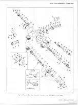
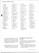
(Refer to Figures 1 M and 2M)
R e m o v a l
1. Remove drain plug from axle housing and from differ
ential carrier cover and allow lubricant to drain.
2
. Remove valve from shift lever bracket.
3. Remove Propeller shaft at input and output shafts.
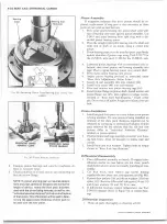
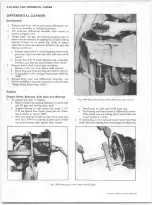
4.
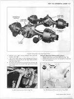
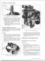
Hold flanges with holding Tool J-3453 or J-8478, then
remove cotter pins from input and output flange nuts
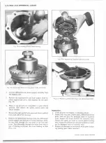
and remove nuts and washers (fig. 3M).
5. Pull flanges from shafts and remove bearing retaining
washer and spacer from axle housing cover.
6
.
Remove axle housing cover nuts and lock washers and
remove cover, oil seal and bearing outer race and roller
assembly from output shaft and housing.
7. The differential carrier cover assembly (includes input
shaft, input shaft bearing, bearing retainer, helical and
differential side gear and inter-axle lock-out shift com
ponents) may now be removed from the differential
carrier, or the cover assembly and differential carrier
assembly may be removed as a unit:
CHEVROLET OVERHAUL M A N U A L SUPPLEMENT
Summary of Contents for 40 60 Series
Page 1: ...40 60 SERIES TRUCK SUPPLEMENT ST 334 72...
Page 86: ......
Page 96: ...n 47 k u m i i i iin I ll II I...
Page 222: ......

