POWER BRAKE CYLINDER 5-15
2.
Inlet valves not badly worn or damaged can be repaired
by lapping valves on a piece of crocus cloth held on a
flat surface.
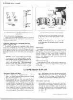
Connecting R o d B u sh in g s
If piston pin bushings in connecting rods require replace
ment, press old bushings out of connecting rods. Press new
bushings in, making sure the oil holes in the bushings line up
A S S E M B L Y OF
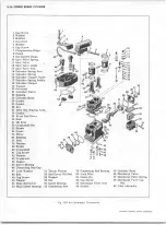
NOTE: Refer to figure 15G while assembling air
compressor.
C r a n k s h a ft In sta lla tio n
Belt-Driven Type
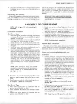
1. Install ball bearing on front of crankshaft. Press bearing
on crankshaft until inner race is seated firmly against
shoulder on crankshaft.
2.
Position thrust washer on the rear end of crankshaft
with oil grooves toward shoulder on shaft.
3. Install rear end cover oil seal in groove of end cover.
4. Install rear end cover and bearing assembly against the
crankcase.
5. Install cap screws and washers attaching end cover to
crankcase. Tighten cap screws firmly.
6
.
Insert crankshaft and front ball bearing, as an assembly,
through crankcase bearing bore and press front ball
bearing into crankcase front bore by using an arbor
press. Make sure that a suitable tool is used to press
bearing and crankshaft assembly into crankcase. The
tool, which can be improvised locally (using a section
of tubing), must press on the outer race of bearing to
insure no shifting of ball bearings or damage to the
bearing assembly. Refer to figure 16G for tool dimen
sions.
CAUTION: Before pressing the bearing and crankshaft
assembly into crankcase, make sure that the crankcase is
properly supported. This will prevent damage to rear cover
pipe plugs or cap screws.
7. Install new oil seal in front bearing cap. Place a new
gasket on bearing cap and slide bearing cap on crank
shaft.
8
. Install cap screws and lock washers attaching end cover
to crankcase. Tighten cap screws firmly.
Gear-Driven Type
1.
Place front thrust washer on crankshaft with oil
grooves toward shoulder on shaft.
2. Insert crankshaft through end cover opening in crank
case.
3. Position rear thrust washer on crankshaft with oil
grooves toward shoulder on shaft.
with the oil passages in the connecting rods. Bushings must
then be reamed, honed, or bored to provide
0
.
0 0 0 1
" to
0
.-
0006" clearance on piston pin. Wipe the bushing, which has
been honed, with a clean cloth to remove all abrasive
material.
IMPORTANT: Make sure not to overlook any of the
above(Cleaning, Inspection, and Repair) items before
assembling the air compressor.
C O M P R E S S O R
4. Install rear end cover oil seal in groove of rear end
cover.
5. Position rear end cover and bearing assembly on crank
shaft until end cover is against the crankcase.
6
. Install cap screws and washers attaching rear end cover
to crankcase. Tighten cap screws.
7. Install key in keyway in front end of crankshaft, install
drive hub on shaft, and secure with nut and cotter pin.
NOTE: Crankshaft should rotate freely.
C ylind er B lo ck In stalla tio n
Place new cylinder block gasket on crankcase. Position
cylinder block on crankcase, aligning marks made before
disassembly. Install cap screws and washers. Tighten firmly.
P isto n a n d C o n n e c tin g Rod A s s e m b ly and
In stallatio n
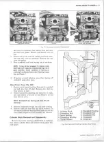
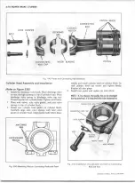
1. Position connecting rod in piston and press piston pin
into piston with lock wire holes in pin aligned with lock
wire holes in piston (refer to fig. 17G). The piston pin
can be rotated by inserting a screwdriver into the piston
pin slot (fig. 18G) to align piston pin lock wire hole with
the lock wire hole in the piston boss.
2. Install new piston pin lock wires in piston pin so that
long end extends through piston and pin. Snap short
end into lock wire hole at bottom of piston skirt.
3. Install piston rings in grooves of pistons. Rings must be
installed in proper location and with pip marks (may be
numbered 1 to 5) upward. Refer to figures 12Gand 13G
for proper clearance dimensions and location of rings
on pistons.
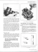
4. Press bearing inserts into rod and cap by hand, with
locating lips in proper alignment.
NOTE: All locating lips are on the same side as cap
bolt (fig. 19G).
5. Lubricate pistons, rings, piston pin bushings, and bear
ing inserts with clean engine oil.
6
. Turn crankshaft to position bearing journal nearest
drive end of crankshaft (No. 1) downward. Remove
bearing cap from N o .l connecting rod.
NOTE: Stagger ring gaps 120 degrees from each other
CHEVROLET OVERHAUL M A N U A L SUPPLEMENT
Summary of Contents for 40 60 Series
Page 1: ...40 60 SERIES TRUCK SUPPLEMENT ST 334 72...
Page 86: ......
Page 96: ...n 47 k u m i i i iin I ll II I...
Page 222: ......

