6M -2 CARBURETORS
Step Number 3
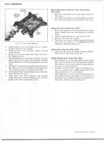
Disconnect the secondary link and move it to one side.
Run the free engine up against the governor to de
termine the amount of over- run that might be ex
pected from the calibration.
Step Number 4
When the problem is suspected to be in the dump valve,
take the vehicle (bob-tailed or empty) out on the
highway and run it up to governed speed and see if
it governs. 150-250 rpm initial over-run is permissi
ble. If it doesn’t govern, disconnect the secondary
diaphragm link and move it to one side; operate the
vehicle again as a two-barrel carburetor. If it gov
erns now, the problem is the dump valve.
NOTE: The secondary control valve is serviced as a
complete assembly. Only part designated w ith part
numbers are available for service. The secondary
control valve cannot be adjusted in the field and
must not be disassembled.
R E P A IR P R O C E D U R E S
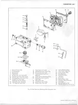
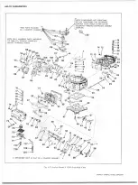
D is a ss e m b ly (Refer to Exploded V ie w Fig. H l l )
NOTE: Do not disassemble carburetor until above
quick checks (Governor Testing) have been comp
leted on the vehicle.
Disassem ble Into Subassem blies
NOTE: Before disassembly, loosen the fuel inlet f it
ting, fuel bowl sight plugs and needle and seat as
sembly lock screws.
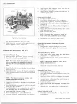
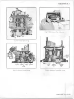
1. Remove primary fuel bowl screws (4) and remove fuel
bowl, metering body, splash shield and gaskets then
remove fuel tube and discard tube seals (fig. H4).
2. Remove secondary fuel bowl screws (4) then remove
fuel bowl, secondary metering body and remove meter
ing body and gaskets.
3. Remove governor control vacuum line.
4. Remove fitting on governor assembly.
5. Remove choke lever and governor cover.
6
. Remove governor spring, governor lever nut and lock
washer, governor assembly to main body screws.
7.
Slide governor assembly off throttle shaft. Remove
throttle shaft seal.
8
.
Remove secondary throttle operating rod "E" ring clip
and remove assembly.
9.
Remove throttle body to main body screw and remove
main body and gasket.
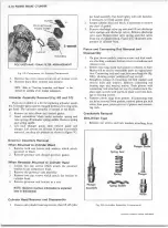
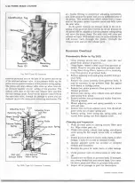
Disassem ble Fuel B o w ls (Fig. H5J
1. Remove float hinge pin retainer and slide float from
bowl then, if necessary, remove spring from float assem
bly.
2.
Remove inlet baffle from bowl.
3.
Remove fuel level sight plugs and gasket.
4.
Remove inlet fitting fuel filter, spring and gaskets.
5.
PRIM ARY BOWL ONLY--
• Remove air vent valve assembly.
• Remove pump diaphragm screws and lift
pump housing, diaphragm and spring from fuel bowl.
•
Check pump inlet ball for free movement and
damage. Damage to ball, passage or retainer requires
new bowl assembly.
Disassem ble M etering Bodies
1.
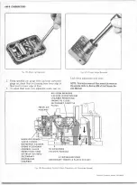
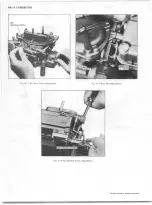
Remove main metering jets with a jet wrench or wide
blade screw dirver (fig. H
6
).
NOTE: A small screw driver w ill distort jet and
change carburetor calibration.
2.
Remove power valves with a 1" 12-point socket (fig.
H7).
3. Remove idle mixture screws and seals from secondary
bowl.
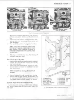
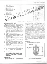
Disassem ble Secondary Throttle Operating
A sse m b ly (Fig. H8, H8a and H9)
1. Remove secondary throttle operating cover screws.
Remove cover, spring, diaphragm and check ball.
2. Remove secondary control valve cover, screws, cover,
spring and diaphragm.
NOTE: Do not disassemble control valve for any
reason
3. Remove clean air filter.
Disassem ble M a in Body
1. Remove choke lever retaining clip and choke rod clip
then remove choke lever spring.
2. Remove pump discharge nozzle screw, nozzle and gas
ket, then up- end the body assembly to remove pump
discharge check valve (fig. H
1 0
).
NOTE: The choke rod seal w ill withstand normal
cleaning in carburetor cleaner, therefore, further
disassembly of the main body is not required for
cleaning purposes. If part replacement is required,
proceed as follows:
CHEVROLET OVERHAUL M A N U A L SUPPLEMENT
Summary of Contents for 40 60 Series
Page 1: ...40 60 SERIES TRUCK SUPPLEMENT ST 334 72...
Page 86: ......
Page 96: ...n 47 k u m i i i iin I ll II I...
Page 222: ......

