DELCOTRON 6Y-1
SECTIO N 6Y
DELCOTRON
CONTENTS OF THIS SECTION
6.2" Series 2D Type 150 Delcotron...........................
"Series 4D Type 150 Delcotron ...........................
6.2" SERIES 2D TYPE 150 DELCOTRON
INDEX
SUBJECT
Disassembly.............................................
Cleaning and Inspection...
PAGE
.......................
6Y-1
.......................
6Y-1
Testing Diodes...........................................
Testing Lamp Method ..........................
....................
6Y-3
....................
6Y-3
Testing Rotor ........................................
G rounds.................................................
....
6
Y
-2
.......................
6Y-3
6Y-3
Ohmmeter M e th o d ................................
Diode Replacement................................
....................
6Y 4
....................
6Y 4
....................
6Y 4
Short Circuits ......................................
.....
6Y-3
Heat Sink Replacement ............................................
6Y-5
Testing S ta to r ........................................
...............
6Y-3
Bearing Replacement ............................ ....................
6Y-5
G rounds................................................. .......................
6Y-3
Drive End F ra m e ................................ ....................
6Y-5
Open Circuits ...................................... .......................
6Y-3
Slip Ring End F ra m e ..............................................
6Y-5
Short Circuits ...................................... .......................
6Y-3
Assembly................................................... ....................
6Y-5
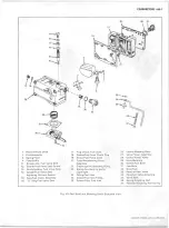
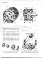
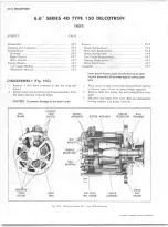
D IS A S S E M B L Y (Figs. 1C and 2C)
1.
Hold generator in a vise, clamping the drive end mount
ing flange lengthwise.
2. Remove two screws securing the cover to the brush
holder and remove cover (fig. 3C).
3.
Remove the nut retaining indicator light wire to the
blade connector post and disconnect wire lead from
post.
4.
Remove two screws retaining the capacitor and brush
holder to rear end frame. Remove brush holder.
NOTE: Capacitor lead is connected inside the gener
ator. Allow capacitor to remain w ith the generator
to avoid undue strain on the lead wire.
5. Remove three slip ring end frame attaching bolts and
tab nuts.
6
.
Carefully pry the end frame and case apart (using a
screw driver) slowly all the way around the circumfer
ence to remove the end frame.
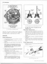
7. Remove the three drive end frame attaching bolts and
tab nuts and remove the end frame, rotor and pulley as
an assembly.
8
. Remove shaft nut, washer, pulley and woodruff key
from rotor shaft, then slide rotor from end frame.
9. Remove drive end frame bearing retainer plate and
bearing from end frame.
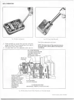
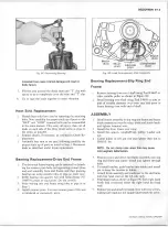
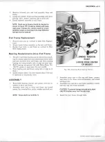
10. To remove slip ring end frame bearing from rotor shaft,
use Tool J-6627 as shown in Figure
8
C.
11. Disconnect the three stator leads by cutting the leads
between coil and diodes (fig.
6
C). An alternate method
is to scrape epoxy coating from lead connections and
unsolder stator leads, using a minimum amount of heat
to avoid damage to diodes.
NOTE: Separating these three leads w ill allow diode
and stator tests outlined in this section.
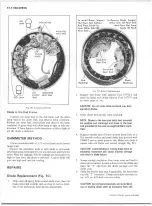
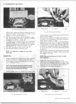
12. Remove heat sink-to-case retaining screws and remove
heat sinks. Insulated heat sink (with batt. terminal)
holds positive diodes.
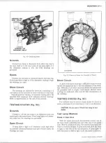
CLEA N IN G A N D IN SP EC T IO N
With generator completely disassembled, except for re
moval of diodes, the components should be cleaned and in
spected. Be sure testing equipment is in good working order
CHEVROLET OVERHAUL M A N U A L SUPPLEMENT
Summary of Contents for 40 60 Series
Page 1: ...40 60 SERIES TRUCK SUPPLEMENT ST 334 72...
Page 86: ......
Page 96: ...n 47 k u m i i i iin I ll II I...
Page 222: ......

