DELCOTRON 6Y-5
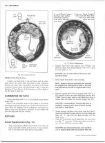
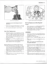
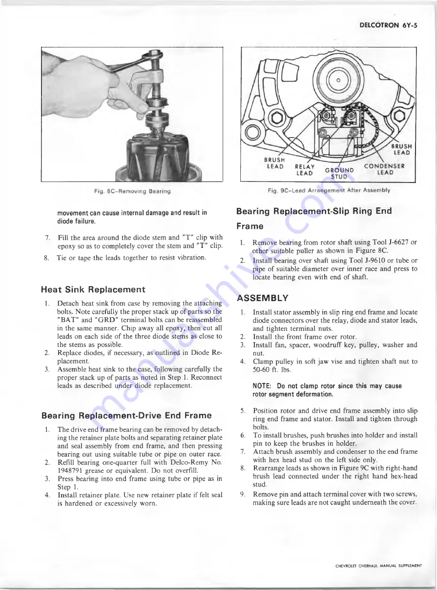
movement can cause internal damage and result in
diode failure.
7. Fill the area around the diode stem and "T" clip with
epoxy so as to completely cover the stem and "T" clip.
8
. Tie or tape the leads together to resist vibration.
Heat Sink Replacement
1.
Detach heat sink from case by removing the attaching
bolts. Note carefully the proper stack up of parts so the
"BAT" and "GRD " terminal bolts can be reassembled
in the same manner. Chip away all epoxy, then cut all
leads on each side of the three diode stems as close to
the stems as possible.
2.
Replace diodes, if necessary, as outlined in Diode Re
placement.
3. Assemble heat sink to the case, following carefully the
proper stack up of parts as noted in Step 1. Reconnect
leads as described under diode replacement.
Bearing Replacement-Drive End Frame
1. The drive end frame bearing can be removed by detach
ing the retainer plate bolts and separating retainer plate
and seal assembly from end frame, and then pressing
bearing out using suitable tube or pipe on outer race.
2. Refill bearing one-quarter full with Delco-Remy No.
1948791 grease or equivalent. Do not overfill.
3.
Press bearing into end frame using tube or pipe as in
Step 1.
4.
Install retainer plate. Use new retainer plate if felt seal
is hardened or excessively worn.
Bearing Replacement-Slip Ring End
Frame
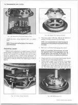
1. Remove bearing from rotor shaft using Tool J-6627 or
other suitable puller as shown in Figure
8
C.
2. Install bearing over shaft using Tool J-9610 or tube or
pipe of suitable diameter over inner race and press to
locate bearing even with end of shaft.
A S S E M B L Y
1. Install stator assembly in slip ring end frame and locate
diode connectors over the relay, diode and stator leads,
and tighten terminal nuts.
2. Install the front frame over rotor.
3.
Install fan, spacer, woodruff key, pulley, washer and
nut.
4.
Clamp pulley in soft jaw vise and tighten shaft nut to
50-60 ft. lbs.
NOTE: Do not clamp rotor since this may cause
rotor segment deformation.
5. Position rotor and drive end frame assembly into slip
ring end frame and stator. Install and tighten through
bolts.
6
. To install brushes, push brushes into holder and install
pin to keep the brushes in holder.
7. Attach brush assembly and condenser to the end frame
with hex head stud on the left side only.
8
.
Rearrange leads as shown in Figure 9C with right-hand
brush lead connected under the right hand hex-head
stud.
9.
Remove pin and attach terminal cover with two screws,
making sure leads are not caught underneath the cover.
CHEVROLET OVERHAUL M A N U A L SUPPLEMENT
Summary of Contents for 40 60 Series
Page 1: ...40 60 SERIES TRUCK SUPPLEMENT ST 334 72...
Page 86: ......
Page 96: ...n 47 k u m i i i iin I ll II I...
Page 222: ......

