S e c . 6M
P a g e 22
FUEL SYSTEM— GASOLINE ENGINES
then se ttle to governed speed which is a norm al
condition.
2.
If th ere is no governor control, perform
the following:
a. D isconnect the vacuum lin e (d istrib u to r-to -
g overn or throttle actuating unit). L eave the seco n d
ary control valve vacuum line connected. Operate
the engine at 2200 rpm, then wet your fin ger and
hold it over the opening in the d isconnected vacuum
lin e . If the engine sp eed slo w s to near id le, the
govern or trouble is in the distributor spinner valve
o r the lin e s or connections to the d istributor. If the
engine does not slow down p roceed to Step b. fo l
lowing:
b. D isconnect the secondary control valve
vacuum lin e from the governor a sse m b ly . Again,
op erate the engine at 2200 rpm and p la ce a wet
fin g er over the p a ssa g e to the governor throttle
unit. If the engine now slo w s to near id le, the prob
le m is in the secondary control valve or its vacuum
lin e . If the engine does not slow down, the problem
is in the governor throttle unit or the vacuum p a s s
a g e s behind it.
3.
If the engine govern s at light load and does
not govern at w ide-open throttle the problem is
probably in the secondary control valve. C orrect
operation of the secondary throttle sy ste m and the
governor depends upon proper functioning of the
secon d ary control v alve. B e su re the secondary
control valve a ir clea n er is cleaned or replaced at
regu lar in terv a ls depending on se v e r ity of o p er
ation, then p erform the following:
When the problem is su sp ected to be in the
secon d ary control valve, operate the v eh icle on the
highway and check governor operation. The gov
ernor should lim it speed to that sp ecified in "Speci
fication s" p lu s 150-250 rpm in itial overrun. If the
engine does not govern, rem ove "E" clip , d iscon
nect the secondary th rottle diaphragm link from
the secon d ary throttle shaft le v e r . Operate the
v eh icle again on only the prim ary carburetor ven
tu r is . If the engine govern s now, the problem is in
the secon d ary control valve which m ust be replaced
a s an a sse m b ly .
ROCHESTER CARBURETORS
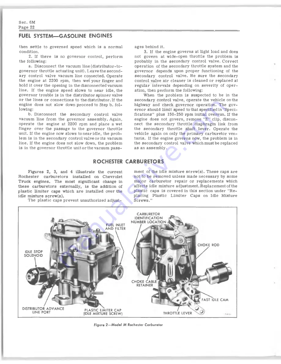
F ig u res 2, 3, and 4 illu str a te the current
R o ch ester
carb u reto rs
in sta lle d on C hevrolet
T ruck en gin es. The m o st sig n ifica n t change in
th e s e carb u retors ex tern a lly , is the addition of
p la s tic lim ite r caps which a re in sta lle d over the
id le m ixture sc r e w (s).
The p la stic caps prevent unauthorized adjust
m ent of the id le m ixture sc r e w (s). T h ese caps are
not to be rem oved u n le ss made n e c e ssa r y by som e
m ajor carburetor rep air or rep lacem en ts which
a ffects id le m ixture adjustm ent. R eplacem ent of the
p la stic caps is covered in th is sectio n under "Re
placing P la s tic L im iter Caps on Idle M ixture
S crew s."
CARBURETOR
IDENTIFICATION
FUEL INLET
A N D FILTER
CHOKE ROD
IDLE STOP
SO LEN O ID
DISTRIBUTOR A D V A N C E
LINE PORT
PLASTIC LIMITER CAP
(IDLE MIXTURE SCREW)
CHO KE
RETAINER
FAST IDLE C A M
THROTTLE LEVER
Figure 2 — M o d e l M Rochester Carburetor


