Sec. 7A
Page 45
SECTION 7
*
7
\anA M uA A io-n c u iJ l G lu tc h e i
A ll inform ation in S ervice Manual S T -331-71 pertaining to TRANS
MISSIONS AND CLUTCHES is applicable to m od els cov ered by this
supplem ent with the addition of the following:
SECTION 7A
GanfruU Jlinkacje.
LINKAGE ADJUSTMENT
(AT475 TRANSMISSION)
MANUAL SHIFT LINKAGE ADJUSTMENT
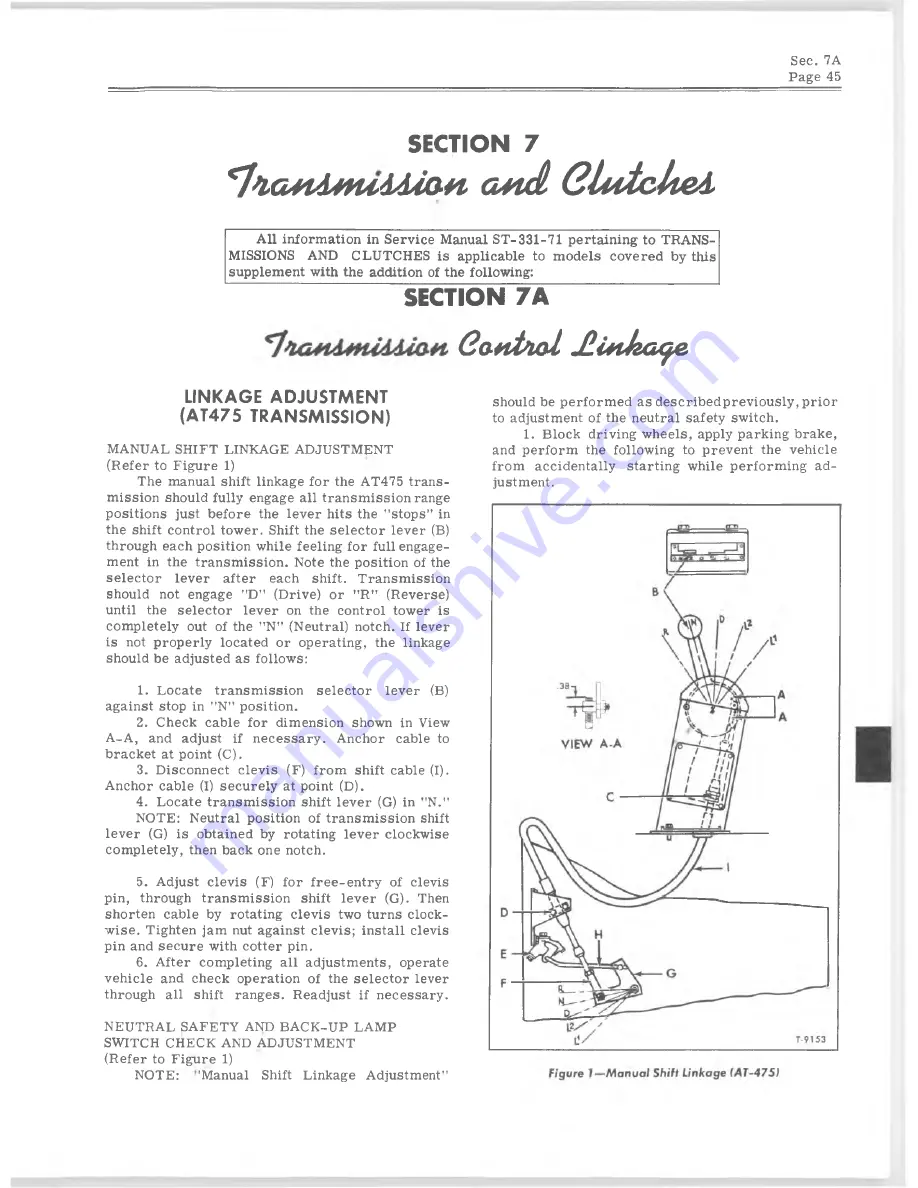
(R efer to Figure 1)
The manual shift linkage for the AT475 tran s
m issio n should fully engage a ll tr a n sm issio n range
p o sitio n s just before the le v e r hits the " stop s” in
the shift control tow er. Shift the se le c to r lev er (B)
through each p osition w hile feelin g for full engage
ment in the tr a n sm issio n . Note the p osition of the
se le c to r le v e r after each sh ift. T ra n sm issio n
should not engage ”D" (Drive) or ”R ” (R everse)
until the s e le c to r le v e r on the control tower is
com pletely out of the "N" (Neutral) notch. If lever
is not properly located or operating, the linkage
should be adjusted as follow s:
1. L ocate tr a n sm issio n se le c to r le v e r (B)
against stop in "N" p osition.
2. Check cable for dim ension shown in View
A -A , and adjust if n e c e ssa r y . Anchor cable to
bracket at point (C).
3. D iscon n ect c le v is (F) from shift cable (I).
Anchor cable (I) se c u r e ly at point (D).
4. L ocate tra n sm issio n shift le v e r (G) in ”N .”
NOTE: N eutral p osition of tr a n sm issio n shift
le v e r (G) is obtained by rotating le v e r clockw ise
com p letely, then back one notch.
5. Adjust c le v is (F) for fr e e -e n tr y of clev is
pin, through tr a n sm issio n shift le v e r (G). Then
shorten cable by rotating c le v is two turns clock
w ise . Tighten jam nut against c le v is; in sta ll clev is
pin and se c u r e with cotter pin.
6. A fter com pleting a ll adjustm ents, operate
v e h ic le and check operation of the se le c to r lever
through a ll shift ran ges. Readjust if n e c e ssa r y .
NEUTRAL SAFETY AND BACK-UP LAMP
SWITCH CHECK AND ADJUSTMENT
(R efer to Figure 1)
NOTE: -'Manual Shift Linkage Adjustm ent”
should be perform ed a s d e scr ib ed p r ev io u sly , p rior
to adjustm ent of the neutral safety sw itch.
1.
B lock driving w h eels, apply parking brake,
and perform the follow ing to prevent the veh icle
from accid en tally startin g w hile perform ing ad
justm ent.


