S ec. 3
P a g e 3
SECTION 3
S u d s K t& n d A X U l
SECTION 3A
fy n x w
U
A
U
<
f* u n e +
tt
A ll inform ation and alignm ent in stru ctio n s in S e r v ic e Manual
S T -3 3 1 -7 1 "FRONT END ALIGNMENT” (SEC. 3A) are applicable
to m od els co v ered by th is supplem ent.
SECTION 3B
A xle.
A ll front axle inform ation in S e r v ic e Manual S T -331-71 "FRONT
AXLE” (SEC. 3B) i s applicable to m od els co v ere d by th is supplem ent.
A ll front axle inform ation for the F -1 2 0 ax le is a ls o applicable to the
F -1 1 0 a x le. Illu stra tio n s and s p e c ific a tio n s have been updated.
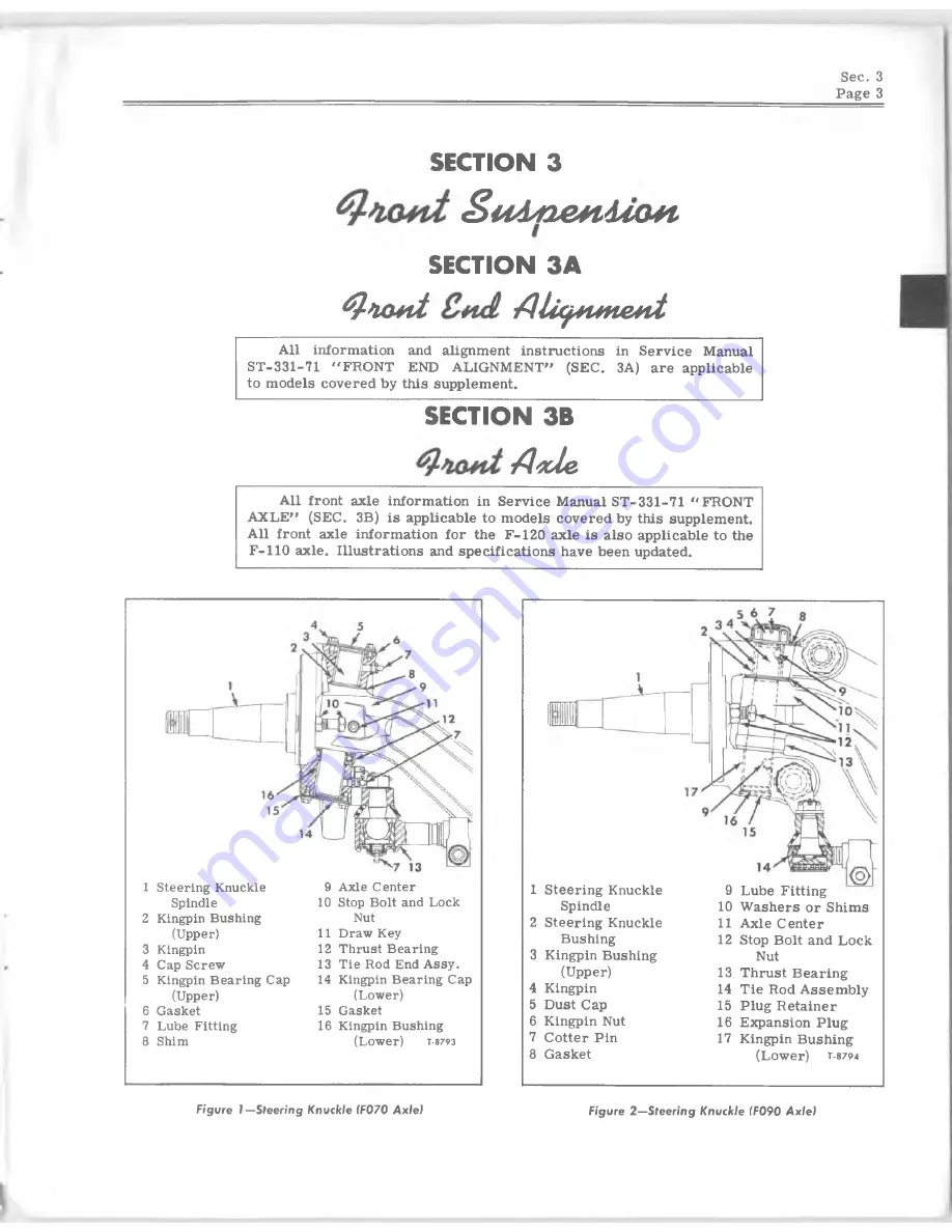
1 Steering Knuckle
9 Axle Center
Spindle
10 Stop Bolt and Lock
2 Kingpin Bushing
Nut
(Upper)
11 Draw Key
3 Kingpin
12 Thrust Bearing
4 Cap Screw
13 Tie Rod End A ssy.
5 Kingpin Bearing Cap
14 Kingpin Bearing Cap
(Upper)
(Lower)
6 Gasket
15 Gasket
7 Lube Fitting
16 Kingpin Bushing
8 Shim
(Lower)
t
-8793
1 S teerin g Knuckle
Spindle
2 Steerin g Knuckle
Bushing
3 Kingpin Bushing
(Upper)
4 Kingpin
5 D ust Cap
6 Kingpin Nut
7 C otter Pin
8 G asket
9 Lube Fitting
10 W ashers or Shim s
11 A xle C enter
12 Stop B olt and Lock
Nut
13 T hrust B earin g
14 T ie Rod A sse m b ly
15 Plug R etain er
16 Ejqpansion P lug
17 Kingpin B ushing
(Lower)
t
-8794
Fig u re 1 —Steering K n uckle (F0 7 0 A x le )
Figure 2 —Steering K n uckle (F090 A x le )


