1 B-6 BODY
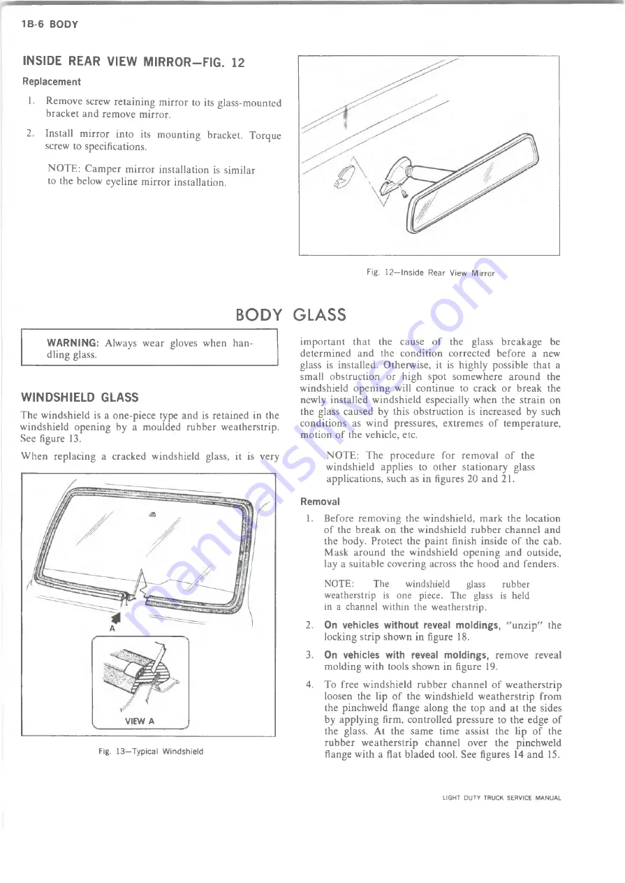
INSIDE REAR VIEW MIRROR—FIG. 12
Replacement
1. Remove screw retaining mirror to its glass-mounted
bracket and remove mirror.
2. Install mirror into its mounting bracket. Torque
screw to specifications.
NOTE: Camper mirror installation is similar
to the below eyeline mirror installation.
Fig. 12—Inside Rear View Mirror
BODY
WARNING:
Always wear gloves when han
dling glass.
WINDSHIELD GLASS
The windshield is a one-piece type and is retained in the
windshield opening by a moulded rubber weatherstrip.
See figure 13.
When replacing a cracked windshield glass, it is very
Fig. 13—Typical Windshield
GLASS
important that the cause of the glass breakage be
determined and the condition corrected before a new
glass is installed. Otherwise, it is highly possible that a
small obstruction or high spot somewhere around the
windshield opening will continue to crack or break the
newly installed windshield especially when the strain on
the glass caused by this obstruction is increased by such
conditions as wind pressures, extremes of temperature,
motion of the vehicle, etc.
NOTE: The procedure for removal of the
windshield applies to other stationary glass
applications, such as in figures 20 and 21.
Removal
1. Before removing the windshield, mark the location
of the break on the windshield rubber channel and
the body. Protect the paint finish inside of the cab.
Mask around the windshield opening and outside,
lay a suitable covering across the hood and fenders.
NOTE:
The windshield glass rubber
weatherstrip is one piece. The glass is held
in a channel within the weatherstrip.
2.
On vehicles without reveal moldings,
"unzip" the
locking strip shown in figure 18.
3.
On vehicles with reveal moldings,
remove reveal
molding with tools shown in figure 19.
4. To free windshield rubber channel of weatherstrip
loosen the lip of the windshield weatherstrip from
the pinchweld flange along the top and at the sides
by applying firm, controlled pressure to the edge of
the glass. At the same time assist the lip of the
rubber weatherstrip channel over the pinchweld
flange with a flat bladed tool. See figures 14 and 15.
VIEW A
LIGHT DUTY TRUCK SERVICE MANUAL
Summary of Contents for Light Duty Truck 1973
Page 1: ......
Page 4: ......
Page 6: ......
Page 53: ...HEATER AND AIR CONDITIONING 1A 27 LIGHT DUTY TRUCK SERVICE MANUAL...
Page 115: ...LIGHT DUTY TRUCK SERVICE M A N U A L HEATER AND AIR CONDITIONING 1A 89...
Page 123: ...BODY 1B 3 Fig 6 Typical 06 Van LIGHT DUTY TRUCK SERVICE MANUAL...
Page 149: ...BODY 1B 29 Fig 84 Body Mounting 06 Fig 85 Body Mounting 14 LIGHT DUTY TRUCK SERVICE MANUAL...
Page 171: ...LIGHT DUTY TRUCK SERVICE M A N U A L Fig 2 Frame Horizontal Checking Typical FRAME 2 3...
Page 173: ...LIGHT DUTY TRUCK SERVICE M A N U A L Fig 4 10 30 Series Truck Frame FRAME 2 5...
Page 174: ...2 6 FRAME LIGHT DUTY TRUCK SERVICE MANUAL Fig 5 Underbody Reference Points G Van...
Page 185: ...FRONT SUSPENSION 3 11 Fig 16 Toe out on Turns LIGHT DUTY TRUCK SERVICE MANUAL...
Page 224: ......
Page 266: ......
Page 351: ...ENGINE 6 15 Fig ID Sectional View of Eight Cylinder Engine LIGHT DUTY TRUCK SERVICE MANUAL...
Page 375: ...EN G IN E 6 39 LIGHT DUTY TRUCK SERVICE MANUAL...
Page 376: ...6 4 0 ENGINE LIGHT DUTY TRUCK SERVICE MANUAL...
Page 377: ...ENG IN E 6 41 LIGHT DUTY TRUCK SERVICE MANUAL...
Page 378: ...LIGHT DUTY TRUCK SERVICE MANUAL Fig 37L K Series Engine Front Mount 6 42 ENG INE...
Page 400: ...6 6 4 ENG INE LIGHT DUTY TRUCK SERVICE MANUAL...
Page 401: ...ENG IN E 6 65 LIGHT DUTY TRUCK SERVICE MANUAL...
Page 402: ...6 6 6 ENGINE LIGHT DUTY TRUCK SERVICE MANUAL...
Page 403: ...E NG IN E 6 67 Fig 36V C Series Engine Mounts LIGHT DUTY TRUCK SERVICE MANUAL...
Page 410: ......
Page 423: ...EN G IN E C OOLING 6K 13 Fig 16 Overheating Chart LIGHT DUTY TRUCK SERVICE MANUAL...
Page 424: ...6 K 1 4 ENG INE COOLING Fig 17 Coolant Loss Chart LIGHT DUTY TRUCK SERVICE MANUAL...
Page 456: ...6M 32 ENGINE FUEL Fig K15 Accelerator Controls G Van L 6 LIGHT DUTY TRUCK SERVICE MANUAL...
Page 492: ......
Page 512: ...Fig 18e Vacuum Advance Diagram V8 Engine...
Page 516: ...6 T 2 4 E M IS S IO N CONTROL SYSTEMS LIGHT DUTY TRUCK SERVICE MANUAL...
Page 528: ......
Page 590: ......
Page 593: ...CLUTCHES MANUAL TRANSMISSIONS 7M 3 LIGHT DUTY TRUCK SERVICE MANUAL...
Page 598: ...7M 8 CLUTCHES MANUAL TRANSMISSIONS LIGHT DUTY TRUCK SERVICE MANUAL...
Page 642: ......
Page 654: ......
Page 743: ...FUEL TANKS AND EXHAUST 8 13 LIGHT DUTY TRUCK SERVICE MANUAL...
Page 744: ...8 14 FUEL TANKS AND EXHAUST LIGHT DUTY TRUCK SERVICE MANUAL...
Page 760: ...8 30 FUEL TANKS AND EXHAUST Fig 40 Exhaust Pipe P Models LIGHT DUTY TRUCK SERVICE MANUAL...
Page 761: ...FUEL TANKS AND EXHAUST 8 31 LIGHT DUTY TRUCK SERVICE MANUAL...
Page 763: ...FUEL TANKS AND EXHAUST 8 33 LIGHT DUTY TRUCK SERVICE MANUAL...
Page 766: ......
Page 832: ...LIGHT DUTY TRUCK SERVICE MANUAL Fig 106 Power Steering Pump Mounting Typical 9 66 STEERING...
Page 833: ...PUMP ASSEMBLY STEERING GEAR TYPICAL SMALL V8 TYPICAL LARGE V8 STEERING 9 67...
Page 861: ...STEERING 9 95 Fig 134 Power Steering Pump Leakage LIGHT DUTY TRUCK SERVICE MANUAL...
Page 864: ......
Page 876: ......
Page 886: ...11 10 CHASSIS SHEET METAL LIGHT DUTY TRUCK SERVICE MANUAL...
Page 891: ...ELECTRICAL BODY AND CHASSIS 12 5 LIGHT DUTY TRUCK SERVICE MANUAL...
Page 934: ......
Page 942: ......
Page 970: ......
Page 972: ......
Page 974: ......
Page 976: ...V...
Page 978: ......
Page 979: ......


