REAR S U S P E N S IO N A N D DRIV ELINE
4 -9
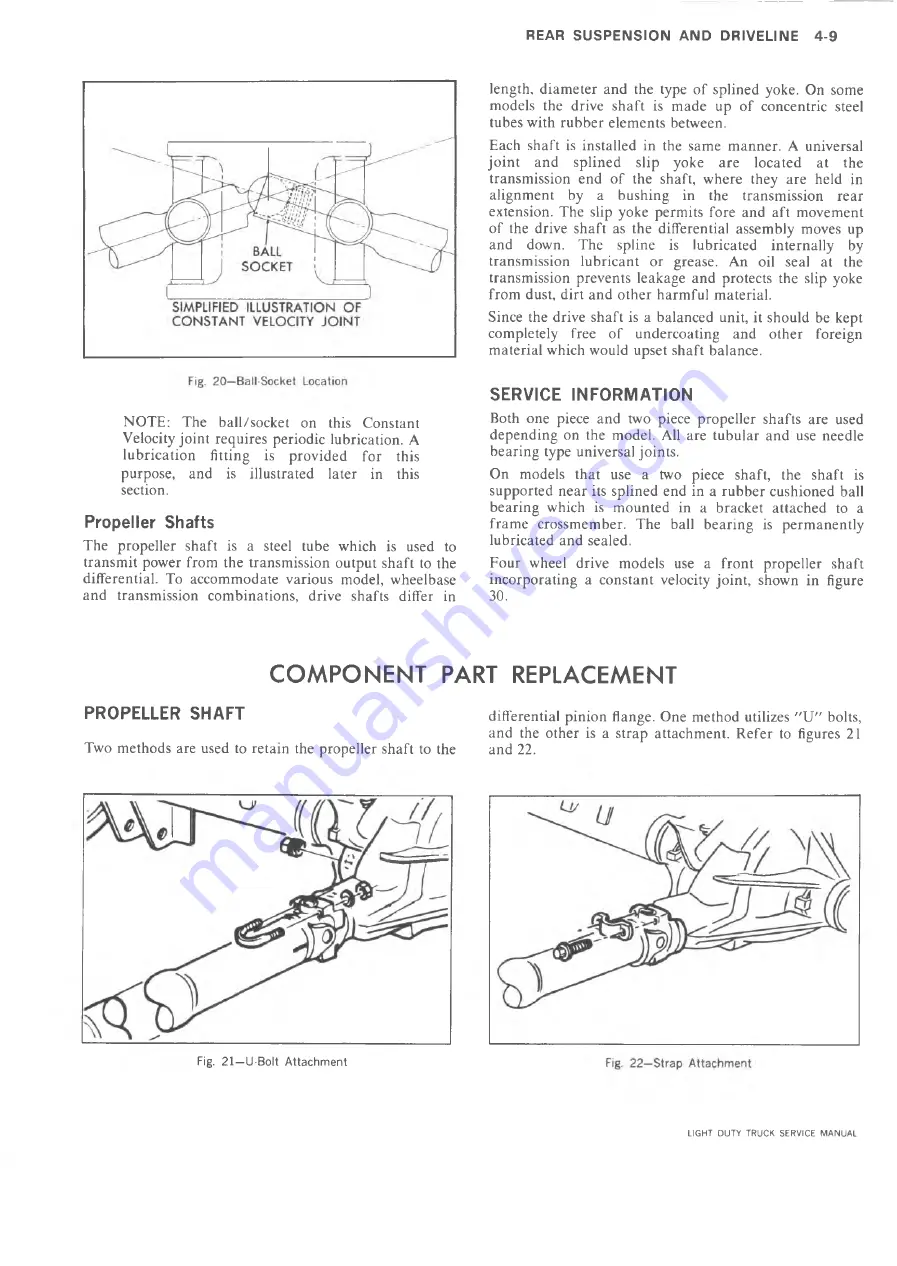
NOTE: The ball/socket on this Constant
Velocity joint requires periodic lubrication. A
lubrication fitting is provided for this
purpose, and is illustrated later in this
section.
Propeller Shafts
The propeller shaft is a steel tube which is used to
transmit power from the transmission output shaft to the
differential. To accommodate various model, wheelbase
and transmission combinations, drive shafts differ in
length, diameter and the type of splined yoke. On some
models the drive shaft is made up of concentric steel
tubes with rubber elements between.
Each shaft is installed in the same manner. A universal
joint and splined slip yoke are located at the
transmission end of the shaft, where they are held in
alignment by a bushing in the transmission rear
extension. The slip yoke permits fore and aft movement
of the drive shaft as the differential assembly moves up
and down. The spline is lubricated internally by
transmission lubricant or grease. An oil seal at the
transmission prevents leakage and protects the slip yoke
from dust, dirt and other harmful material.
Since the drive shaft is a balanced unit, it should be kept
completely free of undercoating and other foreign
material which would upset shaft balance.
SERVICE INFORMATION
Both one piece and two piece propeller shafts are used
depending on the model. All are tubular and use needle
bearing type universal joints.
On models that use a two piece shaft, the shaft is
supported near its splined end in a rubber cushioned ball
bearing which is mounted in a bracket attached to a
frame crossmember. The ball bearing is permanently
lubricated and sealed.
Four wheel drive models use a front propeller shaft
incorporating a constant velocity joint, shown in figure
30.
C O M P O N E N T PART REPLACEMENT
PROPELLER SHAFT
Two methods are used to retain the propeller shaft to the
Fig. 21—U-Bolt Attachment
differential pinion flange. One method utilizes "U " bolts,
and the other is a strap attachment. Refer to figures 21
and
22
.
LIGHT DUTY TRUCK SERVICE MANUAL
Summary of Contents for Light Duty Truck 1973
Page 1: ......
Page 4: ......
Page 6: ......
Page 53: ...HEATER AND AIR CONDITIONING 1A 27 LIGHT DUTY TRUCK SERVICE MANUAL...
Page 115: ...LIGHT DUTY TRUCK SERVICE M A N U A L HEATER AND AIR CONDITIONING 1A 89...
Page 123: ...BODY 1B 3 Fig 6 Typical 06 Van LIGHT DUTY TRUCK SERVICE MANUAL...
Page 149: ...BODY 1B 29 Fig 84 Body Mounting 06 Fig 85 Body Mounting 14 LIGHT DUTY TRUCK SERVICE MANUAL...
Page 171: ...LIGHT DUTY TRUCK SERVICE M A N U A L Fig 2 Frame Horizontal Checking Typical FRAME 2 3...
Page 173: ...LIGHT DUTY TRUCK SERVICE M A N U A L Fig 4 10 30 Series Truck Frame FRAME 2 5...
Page 174: ...2 6 FRAME LIGHT DUTY TRUCK SERVICE MANUAL Fig 5 Underbody Reference Points G Van...
Page 185: ...FRONT SUSPENSION 3 11 Fig 16 Toe out on Turns LIGHT DUTY TRUCK SERVICE MANUAL...
Page 224: ......
Page 266: ......
Page 351: ...ENGINE 6 15 Fig ID Sectional View of Eight Cylinder Engine LIGHT DUTY TRUCK SERVICE MANUAL...
Page 375: ...EN G IN E 6 39 LIGHT DUTY TRUCK SERVICE MANUAL...
Page 376: ...6 4 0 ENGINE LIGHT DUTY TRUCK SERVICE MANUAL...
Page 377: ...ENG IN E 6 41 LIGHT DUTY TRUCK SERVICE MANUAL...
Page 378: ...LIGHT DUTY TRUCK SERVICE MANUAL Fig 37L K Series Engine Front Mount 6 42 ENG INE...
Page 400: ...6 6 4 ENG INE LIGHT DUTY TRUCK SERVICE MANUAL...
Page 401: ...ENG IN E 6 65 LIGHT DUTY TRUCK SERVICE MANUAL...
Page 402: ...6 6 6 ENGINE LIGHT DUTY TRUCK SERVICE MANUAL...
Page 403: ...E NG IN E 6 67 Fig 36V C Series Engine Mounts LIGHT DUTY TRUCK SERVICE MANUAL...
Page 410: ......
Page 423: ...EN G IN E C OOLING 6K 13 Fig 16 Overheating Chart LIGHT DUTY TRUCK SERVICE MANUAL...
Page 424: ...6 K 1 4 ENG INE COOLING Fig 17 Coolant Loss Chart LIGHT DUTY TRUCK SERVICE MANUAL...
Page 456: ...6M 32 ENGINE FUEL Fig K15 Accelerator Controls G Van L 6 LIGHT DUTY TRUCK SERVICE MANUAL...
Page 492: ......
Page 512: ...Fig 18e Vacuum Advance Diagram V8 Engine...
Page 516: ...6 T 2 4 E M IS S IO N CONTROL SYSTEMS LIGHT DUTY TRUCK SERVICE MANUAL...
Page 528: ......
Page 590: ......
Page 593: ...CLUTCHES MANUAL TRANSMISSIONS 7M 3 LIGHT DUTY TRUCK SERVICE MANUAL...
Page 598: ...7M 8 CLUTCHES MANUAL TRANSMISSIONS LIGHT DUTY TRUCK SERVICE MANUAL...
Page 642: ......
Page 654: ......
Page 743: ...FUEL TANKS AND EXHAUST 8 13 LIGHT DUTY TRUCK SERVICE MANUAL...
Page 744: ...8 14 FUEL TANKS AND EXHAUST LIGHT DUTY TRUCK SERVICE MANUAL...
Page 760: ...8 30 FUEL TANKS AND EXHAUST Fig 40 Exhaust Pipe P Models LIGHT DUTY TRUCK SERVICE MANUAL...
Page 761: ...FUEL TANKS AND EXHAUST 8 31 LIGHT DUTY TRUCK SERVICE MANUAL...
Page 763: ...FUEL TANKS AND EXHAUST 8 33 LIGHT DUTY TRUCK SERVICE MANUAL...
Page 766: ......
Page 832: ...LIGHT DUTY TRUCK SERVICE MANUAL Fig 106 Power Steering Pump Mounting Typical 9 66 STEERING...
Page 833: ...PUMP ASSEMBLY STEERING GEAR TYPICAL SMALL V8 TYPICAL LARGE V8 STEERING 9 67...
Page 861: ...STEERING 9 95 Fig 134 Power Steering Pump Leakage LIGHT DUTY TRUCK SERVICE MANUAL...
Page 864: ......
Page 876: ......
Page 886: ...11 10 CHASSIS SHEET METAL LIGHT DUTY TRUCK SERVICE MANUAL...
Page 891: ...ELECTRICAL BODY AND CHASSIS 12 5 LIGHT DUTY TRUCK SERVICE MANUAL...
Page 934: ......
Page 942: ......
Page 970: ......
Page 972: ......
Page 974: ......
Page 976: ...V...
Page 978: ......
Page 979: ......


