5 -4 2 BRAKES
I f Switch Circuit is Closed
a. Rotate switch bracket rearward until switch "just
opens" (light off).
b. Hold switch bracket in this position and tighten
bolt (D). Switch should close (light on) at 5.10"
brake pedal pad movement from full back.
I f Switch Circuit is Open
a. Rotate switch bracket forward until switch "just
closes" (light on).
b. Hold switch bracket in this position and tighten
bolt (D).
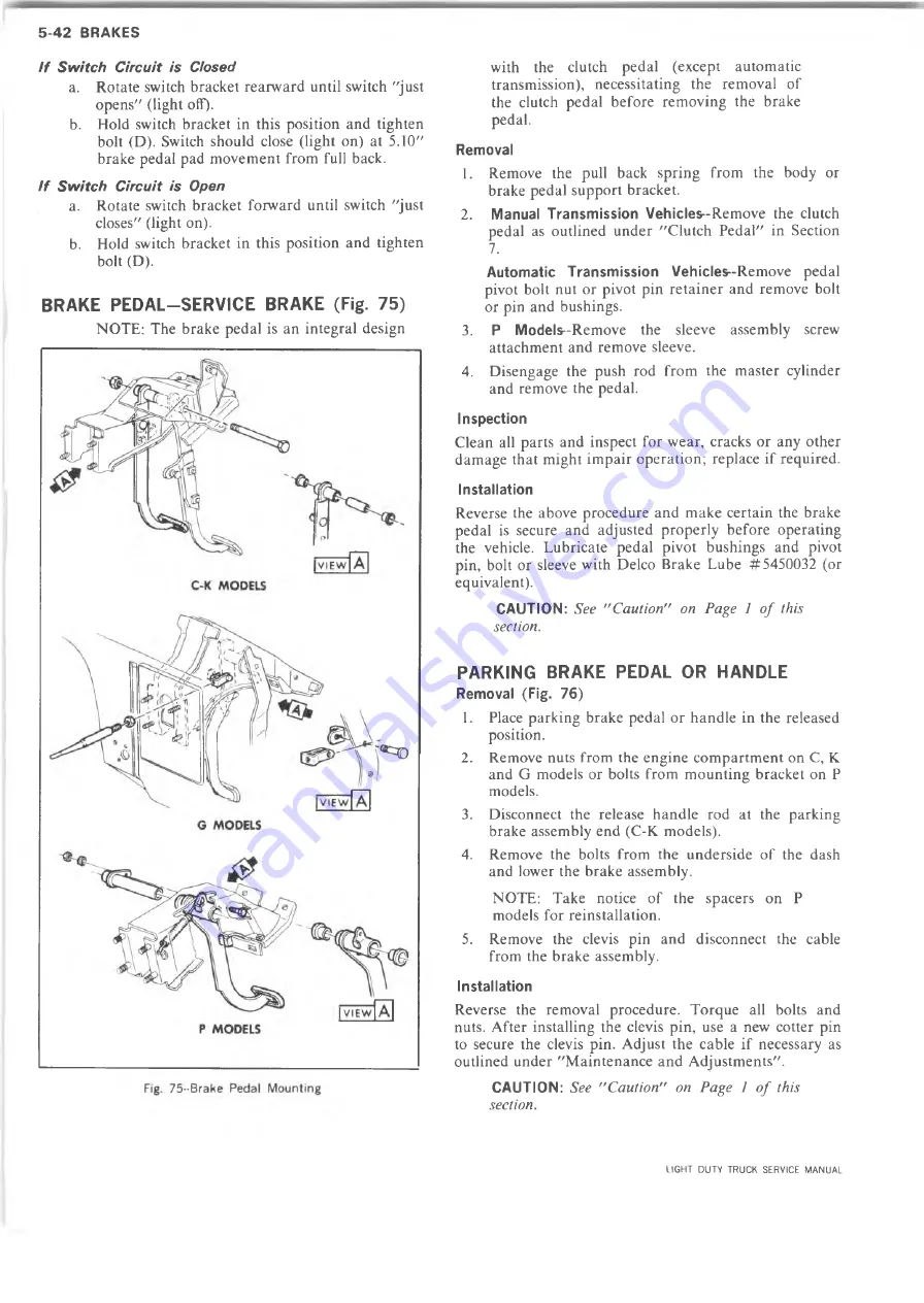
BRAKE PEDAL—SERVICE BRAKE (Fig. 75)
NOTE: The brake pedal is an integral design
with the clutch pedal (except automatic
transmission), necessitating the removal of
the clutch pedal before removing the brake
pedal.
Removal
1. Remove the pull back spring from the body or
brake pedal support bracket.
2.
Manual Transm ission Vehicles-Rem ove
the clutch
pedal as outlined under "Clutch Pedal" in Section
7.
Automatic Transm ission Vehicles-Rem ove
pedal
pivot bolt nut or pivot pin retainer and remove bolt
or pin and bushings.
3.
P Models-Remove
the sleeve assembly screw
attachment and remove sleeve.
4. Disengage the push rod from the master cylinder
and remove the pedal.
Inspection
Clean all parts and inspect for wear, cracks or any other
damage that might impair operation; replace if required.
Installation
Reverse the above procedure and make certain the brake
pedal is secure and adjusted properly before operating
the vehicle. Lubricate pedal pivot bushings and pivot
pin, bolt or sleeve with Delco Brake Lube #5450032 (or
equivalent).
CAUTIO N:
See
"
Caution
"
on Page 1 of this
section.
PARKING BRAKE PEDAL OR HANDLE
Removal (Fig. 76)
1. Place parking brake pedal or handle in the released
position.
2. Remove nuts from the engine compartment on C, K
and G models or bolts from mounting bracket on P
models.
3. Disconnect the release handle rod at the parking
brake assembly end (C-K models).
4. Remove the bolts from the underside of the dash
and lower the brake assembly.
NOTE: Take notice of the spacers on P
models for reinstallation.
5. Remove the clevis pin and disconnect the cable
from the brake assembly.
Installation
Reverse the removal procedure. Torque all bolts and
nuts. After installing the clevis pin, use a new cotter pin
to secure the clevis pin. Adjust the cable if necessary as
outlined under "Maintenance and Adjustments".
CAUTIO N:
See "Caution
"
on Page 1 of this
section.
LIGHT DUTY TRUCK SERVICE MANUAL
Summary of Contents for Light Duty Truck 1973
Page 1: ......
Page 4: ......
Page 6: ......
Page 53: ...HEATER AND AIR CONDITIONING 1A 27 LIGHT DUTY TRUCK SERVICE MANUAL...
Page 115: ...LIGHT DUTY TRUCK SERVICE M A N U A L HEATER AND AIR CONDITIONING 1A 89...
Page 123: ...BODY 1B 3 Fig 6 Typical 06 Van LIGHT DUTY TRUCK SERVICE MANUAL...
Page 149: ...BODY 1B 29 Fig 84 Body Mounting 06 Fig 85 Body Mounting 14 LIGHT DUTY TRUCK SERVICE MANUAL...
Page 171: ...LIGHT DUTY TRUCK SERVICE M A N U A L Fig 2 Frame Horizontal Checking Typical FRAME 2 3...
Page 173: ...LIGHT DUTY TRUCK SERVICE M A N U A L Fig 4 10 30 Series Truck Frame FRAME 2 5...
Page 174: ...2 6 FRAME LIGHT DUTY TRUCK SERVICE MANUAL Fig 5 Underbody Reference Points G Van...
Page 185: ...FRONT SUSPENSION 3 11 Fig 16 Toe out on Turns LIGHT DUTY TRUCK SERVICE MANUAL...
Page 224: ......
Page 266: ......
Page 351: ...ENGINE 6 15 Fig ID Sectional View of Eight Cylinder Engine LIGHT DUTY TRUCK SERVICE MANUAL...
Page 375: ...EN G IN E 6 39 LIGHT DUTY TRUCK SERVICE MANUAL...
Page 376: ...6 4 0 ENGINE LIGHT DUTY TRUCK SERVICE MANUAL...
Page 377: ...ENG IN E 6 41 LIGHT DUTY TRUCK SERVICE MANUAL...
Page 378: ...LIGHT DUTY TRUCK SERVICE MANUAL Fig 37L K Series Engine Front Mount 6 42 ENG INE...
Page 400: ...6 6 4 ENG INE LIGHT DUTY TRUCK SERVICE MANUAL...
Page 401: ...ENG IN E 6 65 LIGHT DUTY TRUCK SERVICE MANUAL...
Page 402: ...6 6 6 ENGINE LIGHT DUTY TRUCK SERVICE MANUAL...
Page 403: ...E NG IN E 6 67 Fig 36V C Series Engine Mounts LIGHT DUTY TRUCK SERVICE MANUAL...
Page 410: ......
Page 423: ...EN G IN E C OOLING 6K 13 Fig 16 Overheating Chart LIGHT DUTY TRUCK SERVICE MANUAL...
Page 424: ...6 K 1 4 ENG INE COOLING Fig 17 Coolant Loss Chart LIGHT DUTY TRUCK SERVICE MANUAL...
Page 456: ...6M 32 ENGINE FUEL Fig K15 Accelerator Controls G Van L 6 LIGHT DUTY TRUCK SERVICE MANUAL...
Page 492: ......
Page 512: ...Fig 18e Vacuum Advance Diagram V8 Engine...
Page 516: ...6 T 2 4 E M IS S IO N CONTROL SYSTEMS LIGHT DUTY TRUCK SERVICE MANUAL...
Page 528: ......
Page 590: ......
Page 593: ...CLUTCHES MANUAL TRANSMISSIONS 7M 3 LIGHT DUTY TRUCK SERVICE MANUAL...
Page 598: ...7M 8 CLUTCHES MANUAL TRANSMISSIONS LIGHT DUTY TRUCK SERVICE MANUAL...
Page 642: ......
Page 654: ......
Page 743: ...FUEL TANKS AND EXHAUST 8 13 LIGHT DUTY TRUCK SERVICE MANUAL...
Page 744: ...8 14 FUEL TANKS AND EXHAUST LIGHT DUTY TRUCK SERVICE MANUAL...
Page 760: ...8 30 FUEL TANKS AND EXHAUST Fig 40 Exhaust Pipe P Models LIGHT DUTY TRUCK SERVICE MANUAL...
Page 761: ...FUEL TANKS AND EXHAUST 8 31 LIGHT DUTY TRUCK SERVICE MANUAL...
Page 763: ...FUEL TANKS AND EXHAUST 8 33 LIGHT DUTY TRUCK SERVICE MANUAL...
Page 766: ......
Page 832: ...LIGHT DUTY TRUCK SERVICE MANUAL Fig 106 Power Steering Pump Mounting Typical 9 66 STEERING...
Page 833: ...PUMP ASSEMBLY STEERING GEAR TYPICAL SMALL V8 TYPICAL LARGE V8 STEERING 9 67...
Page 861: ...STEERING 9 95 Fig 134 Power Steering Pump Leakage LIGHT DUTY TRUCK SERVICE MANUAL...
Page 864: ......
Page 876: ......
Page 886: ...11 10 CHASSIS SHEET METAL LIGHT DUTY TRUCK SERVICE MANUAL...
Page 891: ...ELECTRICAL BODY AND CHASSIS 12 5 LIGHT DUTY TRUCK SERVICE MANUAL...
Page 934: ......
Page 942: ......
Page 970: ......
Page 972: ......
Page 974: ......
Page 976: ...V...
Page 978: ......
Page 979: ......


