SECTION 6T
EMISSION CONTROL SYSTEMS
CONTENTS OF THIS SECTION
Positive Crankcase Ventilation..................................... 6T-1
Exhaust Gas Recirculation System............................. 6T-7
Controlled Combustion System.................................... 6T-3
Transmission Controlled Spark System.................... 6T-9
Evaporation Emission Control.....................................
Air Injection Reactor System....................................... 6T-22
POSITIVE CRANKCASE VENTILATION
THEORY OF OPERATION
During the combustion process in a gasoline engine, a
highly corrosive gas is produced. Also, for every gallon
of gasoline burned, more than a gallon of water is
formed. During the last part of the combustion stroke,
some of the unburned fuel and products of combustion
leak past the piston rings into the crankcase. This
leakage is a result of four factors (Fig. la):
1. High combustion chamber pressures.
2. Necessary working clearance of piston rings in their
grooves.
3. Normal ring shifting that sometimes lines up
clearance gaps of two or more rings.
4. Reduction in ring sealing contact area with change
in direction of piston travel.
This blow-by must be removed before it condenses in the
crankcase and reacts with the oil to form sludge which, if
circulated with the oil, will cause corrosive and
accelerated wear of pistons, rings, valves, bearings, etc.
Because this blow-by also carries with it a certain
quantity of unburned fuel, oil dilution will take place if
it is not removed.
These harmful gases are removed from the crankcase
through a system utilizing engine vacuum to draw fresh
air through the crankcase (Fig. 2a).
Fresh air enters the Positive Crankcase Ventilation
(PCV) system from the clean air side of the air cleaner
or through a separate breather filter on the periphery of
the air cleaner.
Since the vacuum supply for the PCV system is from the
intake manifold, the flow through this system into the
manifold must be controlled in such a manner that it
varies in proportion to the regular air-fuel ratio being
drawn into the intake manifold through the carburetor.
The flow through the PCV system into the intake
manifold is regulated by a PCV valve on all engines
(Fig. 3a).
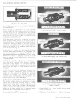
The PCV valve varies the amount of flow through the
system according to the various modes of operation (i.e.
idle, cruise, acceleration etc.). The valve itself consists of
a coil spring, valve, and a two-piece outer body which is
crimped together. The valve dimensions, spring, and
AIR IN T A K E
PCV
C O N T R O L
VA LV E
C R ANKCASE
BLOW BY GASES
K E Y TO PCV SYSTEM
F = F ILT ER E D AIR
B = BLOW BY G A S ES
f
+
b
m nnxnO C O M B U S TIB LE M IX TU R E
Fig. la —Engine Blow-By
Fig. 2a—Schematic of PCV System
LIGHT DUTY TRUCK SERVICE MANUAL
Summary of Contents for Light Duty Truck 1973
Page 1: ......
Page 4: ......
Page 6: ......
Page 53: ...HEATER AND AIR CONDITIONING 1A 27 LIGHT DUTY TRUCK SERVICE MANUAL...
Page 115: ...LIGHT DUTY TRUCK SERVICE M A N U A L HEATER AND AIR CONDITIONING 1A 89...
Page 123: ...BODY 1B 3 Fig 6 Typical 06 Van LIGHT DUTY TRUCK SERVICE MANUAL...
Page 149: ...BODY 1B 29 Fig 84 Body Mounting 06 Fig 85 Body Mounting 14 LIGHT DUTY TRUCK SERVICE MANUAL...
Page 171: ...LIGHT DUTY TRUCK SERVICE M A N U A L Fig 2 Frame Horizontal Checking Typical FRAME 2 3...
Page 173: ...LIGHT DUTY TRUCK SERVICE M A N U A L Fig 4 10 30 Series Truck Frame FRAME 2 5...
Page 174: ...2 6 FRAME LIGHT DUTY TRUCK SERVICE MANUAL Fig 5 Underbody Reference Points G Van...
Page 185: ...FRONT SUSPENSION 3 11 Fig 16 Toe out on Turns LIGHT DUTY TRUCK SERVICE MANUAL...
Page 224: ......
Page 266: ......
Page 351: ...ENGINE 6 15 Fig ID Sectional View of Eight Cylinder Engine LIGHT DUTY TRUCK SERVICE MANUAL...
Page 375: ...EN G IN E 6 39 LIGHT DUTY TRUCK SERVICE MANUAL...
Page 376: ...6 4 0 ENGINE LIGHT DUTY TRUCK SERVICE MANUAL...
Page 377: ...ENG IN E 6 41 LIGHT DUTY TRUCK SERVICE MANUAL...
Page 378: ...LIGHT DUTY TRUCK SERVICE MANUAL Fig 37L K Series Engine Front Mount 6 42 ENG INE...
Page 400: ...6 6 4 ENG INE LIGHT DUTY TRUCK SERVICE MANUAL...
Page 401: ...ENG IN E 6 65 LIGHT DUTY TRUCK SERVICE MANUAL...
Page 402: ...6 6 6 ENGINE LIGHT DUTY TRUCK SERVICE MANUAL...
Page 403: ...E NG IN E 6 67 Fig 36V C Series Engine Mounts LIGHT DUTY TRUCK SERVICE MANUAL...
Page 410: ......
Page 423: ...EN G IN E C OOLING 6K 13 Fig 16 Overheating Chart LIGHT DUTY TRUCK SERVICE MANUAL...
Page 424: ...6 K 1 4 ENG INE COOLING Fig 17 Coolant Loss Chart LIGHT DUTY TRUCK SERVICE MANUAL...
Page 456: ...6M 32 ENGINE FUEL Fig K15 Accelerator Controls G Van L 6 LIGHT DUTY TRUCK SERVICE MANUAL...
Page 492: ......
Page 512: ...Fig 18e Vacuum Advance Diagram V8 Engine...
Page 516: ...6 T 2 4 E M IS S IO N CONTROL SYSTEMS LIGHT DUTY TRUCK SERVICE MANUAL...
Page 528: ......
Page 590: ......
Page 593: ...CLUTCHES MANUAL TRANSMISSIONS 7M 3 LIGHT DUTY TRUCK SERVICE MANUAL...
Page 598: ...7M 8 CLUTCHES MANUAL TRANSMISSIONS LIGHT DUTY TRUCK SERVICE MANUAL...
Page 642: ......
Page 654: ......
Page 743: ...FUEL TANKS AND EXHAUST 8 13 LIGHT DUTY TRUCK SERVICE MANUAL...
Page 744: ...8 14 FUEL TANKS AND EXHAUST LIGHT DUTY TRUCK SERVICE MANUAL...
Page 760: ...8 30 FUEL TANKS AND EXHAUST Fig 40 Exhaust Pipe P Models LIGHT DUTY TRUCK SERVICE MANUAL...
Page 761: ...FUEL TANKS AND EXHAUST 8 31 LIGHT DUTY TRUCK SERVICE MANUAL...
Page 763: ...FUEL TANKS AND EXHAUST 8 33 LIGHT DUTY TRUCK SERVICE MANUAL...
Page 766: ......
Page 832: ...LIGHT DUTY TRUCK SERVICE MANUAL Fig 106 Power Steering Pump Mounting Typical 9 66 STEERING...
Page 833: ...PUMP ASSEMBLY STEERING GEAR TYPICAL SMALL V8 TYPICAL LARGE V8 STEERING 9 67...
Page 861: ...STEERING 9 95 Fig 134 Power Steering Pump Leakage LIGHT DUTY TRUCK SERVICE MANUAL...
Page 864: ......
Page 876: ......
Page 886: ...11 10 CHASSIS SHEET METAL LIGHT DUTY TRUCK SERVICE MANUAL...
Page 891: ...ELECTRICAL BODY AND CHASSIS 12 5 LIGHT DUTY TRUCK SERVICE MANUAL...
Page 934: ......
Page 942: ......
Page 970: ......
Page 972: ......
Page 974: ......
Page 976: ...V...
Page 978: ......
Page 979: ......


