6 Y - 2 E N G IN E E L E C T R IC A L
negative plates into groups. The elements are connected
in series electrically by connectors that pass directly
through the case partitions between cells. The energizer
top is a one piece cover. The cell connectors, by passing
through the cell partitions, connect the elements along
the shortest practical path (fig. 2b). With the length of
the electrical circuit inside the Energizer reduced to a
minimum, the internal voltage drop is decreased
resulting in improved performance, particuarly during
engine cranking at low temperatures.
The terminals of this type Energizer, passing through the
side of the case, are positioned out of the "wet" area
surrounding the vent wells. Normal spillage, spewing,
condensation, and road splash are not as likely to reach
or remain on the vertical sides where the terminals are
located. This greatly decreases the cause of terminal
corrosion. Also, construction of the terminals is such that
the mating cable connector seals the junction and
provides a permanently tight and clean connection.
Power robbing resistance in the form of corrosion is
thereby eliminated at these maintenance-free
connections.
The hard, smooth, one piece cover greatly reduces the
tendency for corrosion to form on the top of the
Energizer. The cover is bonded to the case forming an
air-tight seal between the cover and case.
Electrical energy is released by chemical reactions
between the active materials in the two dissimilar plates
and the electrolyte whenever the Energizer is being
"discharged." Maximum electrical energy is released
only when the cells are being discharged from a state of
full charge.
As • the cells discharge, chemical changes in the active
materials in the plates gradually reduce the potential
electrical energy available. "Recharging" the Energizer
with a flow of direct current opposite to that during
discharge reverses the chemical changes within the cells
and restores them to their active condition and a state of
full charge.
There are two types of Energizers, the "dry charge" type
and the "wet charge" type. The difference in types
depends on the method of manufacture. A "dry charge"
Energizer contains fully charged elements which have
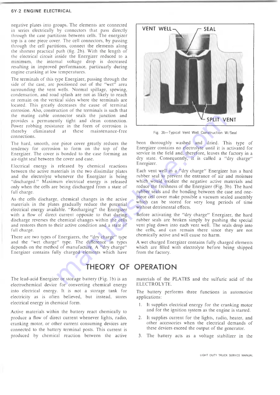
Fig. 3b—Typical Vent Well Construction W/Seal
been thoroughly washed and dried. This type of
Energizer contains no electrolyte until it is activated for
service in the field and, therefore, leaves the factory in a
dry state. Consequently, it is called a "dry charge"
Energizer.
Each vent well in a "dry charge" Energizer has a hard
rubber seal to prevent the entrance of air and moisture
which would oxidize the negative active materials and
reduce the freshness of the Energizer (Fig. 3b). The hard
rubber seals and the bonding between the case and one-
piece cell cover make possible a vacuum sealed assembly
which can be stored for very long periods of time
without detrimental effects.
Before activating the "dry charge" Energizer, the hard
rubber seals are broken simply by pushing the special
vent plug down into each vent well. The seals drop into
the cells, and can remain there since they are not
chemically active and will cause no harm.
A wet charged Energizer contains fully charged elements
which are filled with electrolyte before being shipped
from the factory.
THEORY OF OPERATION
The lead-acid Energizer or storage battery (Fig. lb) is an
electrochemical device for converting chemical energy
into electrical energy. It is not a storage tank for
electricity as is often believed, but instead, stores
electrical energy in chemical form.
Active materials within the battery react chemically to
produce a flow of direct current whenever lights, radio,
cranking motor, or other current consuming devices are
connected to the battery terminal posts. This current is
produced by chemical reaction between the active
materials of the PLATES and the sulfuric acid of the
ELECTROLYTE.
The battery performs three functions in automotive
applications:
1. It supplies electrical energy for the cranking motor
and for the ignition system as the engine is started.
2. It supplies current for the lights, radio, heater, and
other accessories when the electrical demands of
these devices exceed the output of the generator.
3. The battery acts as a voltage stabilizer in the
VEN T WELL
SPLIT VENT
SEAL
LIGHT DUTY TRUCK SERVICE MANUAL
Summary of Contents for Light Duty Truck 1973
Page 1: ......
Page 4: ......
Page 6: ......
Page 53: ...HEATER AND AIR CONDITIONING 1A 27 LIGHT DUTY TRUCK SERVICE MANUAL...
Page 115: ...LIGHT DUTY TRUCK SERVICE M A N U A L HEATER AND AIR CONDITIONING 1A 89...
Page 123: ...BODY 1B 3 Fig 6 Typical 06 Van LIGHT DUTY TRUCK SERVICE MANUAL...
Page 149: ...BODY 1B 29 Fig 84 Body Mounting 06 Fig 85 Body Mounting 14 LIGHT DUTY TRUCK SERVICE MANUAL...
Page 171: ...LIGHT DUTY TRUCK SERVICE M A N U A L Fig 2 Frame Horizontal Checking Typical FRAME 2 3...
Page 173: ...LIGHT DUTY TRUCK SERVICE M A N U A L Fig 4 10 30 Series Truck Frame FRAME 2 5...
Page 174: ...2 6 FRAME LIGHT DUTY TRUCK SERVICE MANUAL Fig 5 Underbody Reference Points G Van...
Page 185: ...FRONT SUSPENSION 3 11 Fig 16 Toe out on Turns LIGHT DUTY TRUCK SERVICE MANUAL...
Page 224: ......
Page 266: ......
Page 351: ...ENGINE 6 15 Fig ID Sectional View of Eight Cylinder Engine LIGHT DUTY TRUCK SERVICE MANUAL...
Page 375: ...EN G IN E 6 39 LIGHT DUTY TRUCK SERVICE MANUAL...
Page 376: ...6 4 0 ENGINE LIGHT DUTY TRUCK SERVICE MANUAL...
Page 377: ...ENG IN E 6 41 LIGHT DUTY TRUCK SERVICE MANUAL...
Page 378: ...LIGHT DUTY TRUCK SERVICE MANUAL Fig 37L K Series Engine Front Mount 6 42 ENG INE...
Page 400: ...6 6 4 ENG INE LIGHT DUTY TRUCK SERVICE MANUAL...
Page 401: ...ENG IN E 6 65 LIGHT DUTY TRUCK SERVICE MANUAL...
Page 402: ...6 6 6 ENGINE LIGHT DUTY TRUCK SERVICE MANUAL...
Page 403: ...E NG IN E 6 67 Fig 36V C Series Engine Mounts LIGHT DUTY TRUCK SERVICE MANUAL...
Page 410: ......
Page 423: ...EN G IN E C OOLING 6K 13 Fig 16 Overheating Chart LIGHT DUTY TRUCK SERVICE MANUAL...
Page 424: ...6 K 1 4 ENG INE COOLING Fig 17 Coolant Loss Chart LIGHT DUTY TRUCK SERVICE MANUAL...
Page 456: ...6M 32 ENGINE FUEL Fig K15 Accelerator Controls G Van L 6 LIGHT DUTY TRUCK SERVICE MANUAL...
Page 492: ......
Page 512: ...Fig 18e Vacuum Advance Diagram V8 Engine...
Page 516: ...6 T 2 4 E M IS S IO N CONTROL SYSTEMS LIGHT DUTY TRUCK SERVICE MANUAL...
Page 528: ......
Page 590: ......
Page 593: ...CLUTCHES MANUAL TRANSMISSIONS 7M 3 LIGHT DUTY TRUCK SERVICE MANUAL...
Page 598: ...7M 8 CLUTCHES MANUAL TRANSMISSIONS LIGHT DUTY TRUCK SERVICE MANUAL...
Page 642: ......
Page 654: ......
Page 743: ...FUEL TANKS AND EXHAUST 8 13 LIGHT DUTY TRUCK SERVICE MANUAL...
Page 744: ...8 14 FUEL TANKS AND EXHAUST LIGHT DUTY TRUCK SERVICE MANUAL...
Page 760: ...8 30 FUEL TANKS AND EXHAUST Fig 40 Exhaust Pipe P Models LIGHT DUTY TRUCK SERVICE MANUAL...
Page 761: ...FUEL TANKS AND EXHAUST 8 31 LIGHT DUTY TRUCK SERVICE MANUAL...
Page 763: ...FUEL TANKS AND EXHAUST 8 33 LIGHT DUTY TRUCK SERVICE MANUAL...
Page 766: ......
Page 832: ...LIGHT DUTY TRUCK SERVICE MANUAL Fig 106 Power Steering Pump Mounting Typical 9 66 STEERING...
Page 833: ...PUMP ASSEMBLY STEERING GEAR TYPICAL SMALL V8 TYPICAL LARGE V8 STEERING 9 67...
Page 861: ...STEERING 9 95 Fig 134 Power Steering Pump Leakage LIGHT DUTY TRUCK SERVICE MANUAL...
Page 864: ......
Page 876: ......
Page 886: ...11 10 CHASSIS SHEET METAL LIGHT DUTY TRUCK SERVICE MANUAL...
Page 891: ...ELECTRICAL BODY AND CHASSIS 12 5 LIGHT DUTY TRUCK SERVICE MANUAL...
Page 934: ......
Page 942: ......
Page 970: ......
Page 972: ......
Page 974: ......
Page 976: ...V...
Page 978: ......
Page 979: ......


