6 Y - 4 E N G IN E E LE C T R IC A L
GENERAL IN FO R M A T IO N
COMMON CAUSES OF FAILURE
Since the Energizer is a perishable item which requires
periodic servicing, a good maintenance program will
insure the longest possible Battery life. If the Energizer
tests good but fails to perform satisfactorily in service
for no apparent reason, the following are some of the
more important factors that may point to the cause of
the trouble.
1. Vehicle accessories inadvertently left on overnight
to cause a discharge condition.
2. Slow speed driving of short duration, to cause an
undercharged condition.
3. A vehicle electrical load exceeding the generator
capacity.
4. Defect in the charging system such as high
resistance, slipping fan belt, faulty generator or
voltage regulator.
5. Battery abuse, including failure to keep the Battery
top clean, cable attaching bolts clean and tight, and
improper addition of water to the cells.
CARE OF ENERGIZER
Energizer Storage
Since the "dry charge" Energizer is vacuum sealed
against the entrance of moisture, it may be stored for
very long periods of time without detrimental effects so
long as the seals remain unbroken. When storing a "dry
charge" Energizer, the following procedures should be
followed:
1. Keep the Energizer in its shipping carton until
activated.
2. Do not stack the "dry charge" Energizer in cartons
more than four high.
3. Rotate stocks regularly.
4. Maintain the storage area at 60°F or higher to aid
activation.
A wet charged Energizer will not maintain its charged
condition during storage, and must be recharged
periodically. During storage, even though the Energizer
is not in use, a slow reaction takes place between the
chemicals inside the Energizer which causes the
Energizer to lose charge and "wear out" slowly. This
reaction is called "self-discharge." The rate at which
self-discharge occurs varies directly with temperature of
the electrolyte.
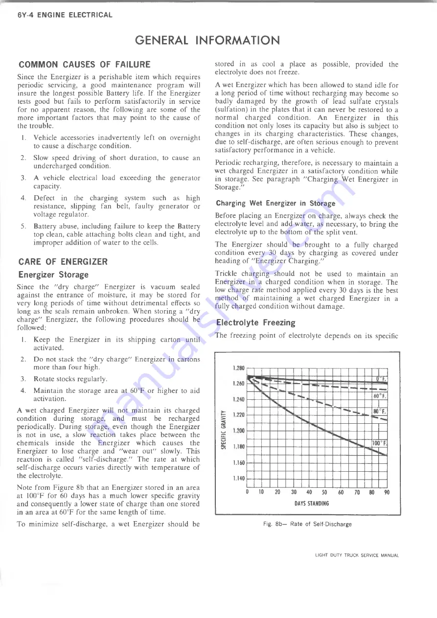
Note from Figure
8
b that an Energizer stored in an area
at 100°F for 60 days has a much lower specific gravity
and consequently a lower state of charge than one stored
in an area at 60°F for the same length of time.
To minimize self-discharge, a wet Energizer should be
stored in as cool a place as possible, provided the
electrolyte does not freeze.
A wet Energizer which has been allowed to stand idle for
a long period of time without recharging may become so
badly damaged by the growth of lead sulfate crystals
(sulfation) in the plates that it can never be restored to a
normal charged condition. An Energizer in this
condition not only loses its capacity but also is subject to
changes in its charging characteristics. These changes,
due to self-discharge, are often serious enough to prevent
satisfactory performance in a vehicle.
Periodic recharging, therefore, is necessary to maintain a
wet charged Energizer in a satisfactory condition while
in storage. See paragraph "Charging Wet Energizer in
Storage."
Charging Wet Energizer in Storage
Before placing an Energizer on charge, always check the
electrolyte level and add water, as necessary, to bring the
electrolyte up to the bottom of the split vent.
The Energizer should be brought to a fully charged
condition every 30 days by charging as covered under
heading of "Energizer Charging."
Trickle charging should not be used to maintain an
Energizer in a charged condition when in storage. The
low charge rate method applied every 30 days is the best
method of maintaining a wet charged Energizer in a
fully charged condition without damage.
Electrolyte Freezing
The freezing point of electrolyte depends on its specific
Fig. 8b— Rate of Self-Discharge
1.160
1.140
0
10
20
30
40
50
60
70
80
90
DAYS STANDING
LIGHT DUTY TRUCK SERVICE MANUAL
Summary of Contents for Light Duty Truck 1973
Page 1: ......
Page 4: ......
Page 6: ......
Page 53: ...HEATER AND AIR CONDITIONING 1A 27 LIGHT DUTY TRUCK SERVICE MANUAL...
Page 115: ...LIGHT DUTY TRUCK SERVICE M A N U A L HEATER AND AIR CONDITIONING 1A 89...
Page 123: ...BODY 1B 3 Fig 6 Typical 06 Van LIGHT DUTY TRUCK SERVICE MANUAL...
Page 149: ...BODY 1B 29 Fig 84 Body Mounting 06 Fig 85 Body Mounting 14 LIGHT DUTY TRUCK SERVICE MANUAL...
Page 171: ...LIGHT DUTY TRUCK SERVICE M A N U A L Fig 2 Frame Horizontal Checking Typical FRAME 2 3...
Page 173: ...LIGHT DUTY TRUCK SERVICE M A N U A L Fig 4 10 30 Series Truck Frame FRAME 2 5...
Page 174: ...2 6 FRAME LIGHT DUTY TRUCK SERVICE MANUAL Fig 5 Underbody Reference Points G Van...
Page 185: ...FRONT SUSPENSION 3 11 Fig 16 Toe out on Turns LIGHT DUTY TRUCK SERVICE MANUAL...
Page 224: ......
Page 266: ......
Page 351: ...ENGINE 6 15 Fig ID Sectional View of Eight Cylinder Engine LIGHT DUTY TRUCK SERVICE MANUAL...
Page 375: ...EN G IN E 6 39 LIGHT DUTY TRUCK SERVICE MANUAL...
Page 376: ...6 4 0 ENGINE LIGHT DUTY TRUCK SERVICE MANUAL...
Page 377: ...ENG IN E 6 41 LIGHT DUTY TRUCK SERVICE MANUAL...
Page 378: ...LIGHT DUTY TRUCK SERVICE MANUAL Fig 37L K Series Engine Front Mount 6 42 ENG INE...
Page 400: ...6 6 4 ENG INE LIGHT DUTY TRUCK SERVICE MANUAL...
Page 401: ...ENG IN E 6 65 LIGHT DUTY TRUCK SERVICE MANUAL...
Page 402: ...6 6 6 ENGINE LIGHT DUTY TRUCK SERVICE MANUAL...
Page 403: ...E NG IN E 6 67 Fig 36V C Series Engine Mounts LIGHT DUTY TRUCK SERVICE MANUAL...
Page 410: ......
Page 423: ...EN G IN E C OOLING 6K 13 Fig 16 Overheating Chart LIGHT DUTY TRUCK SERVICE MANUAL...
Page 424: ...6 K 1 4 ENG INE COOLING Fig 17 Coolant Loss Chart LIGHT DUTY TRUCK SERVICE MANUAL...
Page 456: ...6M 32 ENGINE FUEL Fig K15 Accelerator Controls G Van L 6 LIGHT DUTY TRUCK SERVICE MANUAL...
Page 492: ......
Page 512: ...Fig 18e Vacuum Advance Diagram V8 Engine...
Page 516: ...6 T 2 4 E M IS S IO N CONTROL SYSTEMS LIGHT DUTY TRUCK SERVICE MANUAL...
Page 528: ......
Page 590: ......
Page 593: ...CLUTCHES MANUAL TRANSMISSIONS 7M 3 LIGHT DUTY TRUCK SERVICE MANUAL...
Page 598: ...7M 8 CLUTCHES MANUAL TRANSMISSIONS LIGHT DUTY TRUCK SERVICE MANUAL...
Page 642: ......
Page 654: ......
Page 743: ...FUEL TANKS AND EXHAUST 8 13 LIGHT DUTY TRUCK SERVICE MANUAL...
Page 744: ...8 14 FUEL TANKS AND EXHAUST LIGHT DUTY TRUCK SERVICE MANUAL...
Page 760: ...8 30 FUEL TANKS AND EXHAUST Fig 40 Exhaust Pipe P Models LIGHT DUTY TRUCK SERVICE MANUAL...
Page 761: ...FUEL TANKS AND EXHAUST 8 31 LIGHT DUTY TRUCK SERVICE MANUAL...
Page 763: ...FUEL TANKS AND EXHAUST 8 33 LIGHT DUTY TRUCK SERVICE MANUAL...
Page 766: ......
Page 832: ...LIGHT DUTY TRUCK SERVICE MANUAL Fig 106 Power Steering Pump Mounting Typical 9 66 STEERING...
Page 833: ...PUMP ASSEMBLY STEERING GEAR TYPICAL SMALL V8 TYPICAL LARGE V8 STEERING 9 67...
Page 861: ...STEERING 9 95 Fig 134 Power Steering Pump Leakage LIGHT DUTY TRUCK SERVICE MANUAL...
Page 864: ......
Page 876: ......
Page 886: ...11 10 CHASSIS SHEET METAL LIGHT DUTY TRUCK SERVICE MANUAL...
Page 891: ...ELECTRICAL BODY AND CHASSIS 12 5 LIGHT DUTY TRUCK SERVICE MANUAL...
Page 934: ......
Page 942: ......
Page 970: ......
Page 972: ......
Page 974: ......
Page 976: ...V...
Page 978: ......
Page 979: ......


