HEATER A N D AIR C O N D I T I O N IN G
1A-33
storage of high pressure liquid produced in the
condenser, incorporates a screen sack filled with the
dehydrating agent.
The receiver-dehydrator, used primarily as a liquid
storage tank, also functions to trap minute quantities of
moisture and foreign material which may have remained
in the system after installation or service operations. A
refrigerant sight glass is built into the receiver-
dehydrator to be used as a quick check of the state and
condition of charge of the entire system. The receiver-
dehydrator is mounted near the condenser.
Sight Glass (G and Motor Home Chassis Models)
While having no real function to perform in the system,
the sight glass is a valuable aid in determining whether
or not the refrigerant charge is sufficient and for
eliminating some guess work in diagnosing difficulties.
The sight glass, is built into the receiver-dehydrator
outlet connection and is designed and located so that a
shortage of refrigerant at this point will be indicated by
the appearance of bubbles beneath the glass. The dust
cap provided should be kept in place when the sight
glass is not in use.
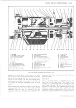
Thermostatic Expansion Valve (Fig. 37)
C-K Overhead, G Floor and Overhead and Motor Home
Chassis systems use a thermostatic expansion valve in
place of a float system.
The valve consists primarily of the power element, body,
actuating pins, seat and orifice. At the high pressure
liquid inlet, is a fine mesh screen which prevents dirt,
filings or other foreign matter from entering the valve
orifice.
When the valve is connected in the system, high pressure
liquid refrigerant enters the valve through the screen
from the receiver-dehydrator or condenser and passes on
to the seat and orifice. Upon passing through the orifice
the high pressure liquid becomes low pressure liquid.
The low pressure liquid leaves the valve and flows into
the evaporator core where it absorbs heat from the
evaporator core and changes to a low pressure vapor,
and leaves the evaporator core as such. The power
element bulb is clamped to the low pressure vapor line
just beyond the outlet of the evaporator (fig. 37).
The operation of the valve is quite simple. It is a matter
of controlling opposing forces produced by a spring and
the refrigerant pressures. For example: The pressure in
the power element is trying to push the seat away from
the orifice, while the adjusting spring is trying to force
the seat toward the orifice. These opposing pressures are
established in the design of the valve so that during idle
periods the adjusting spring tension and the refrigerant
pressure in the cooling coil are always greater than the
opposing pressure in the power element. Therefore, the
valve remains closed. When the compressor is started, it
will reduce the pressure and temperature of the
refrigerant in the cooling coil to a point where the vapor
pressure in the power element becomes the stronger. The
Fig. 37- Expansion Valve
seat then moves off the orifice and liquid starts to flow
through the valve orifice into the cooling coil.
The purpose of the power element is to help determine
the quantity of liquid that is being metered into the
cooling coil. As the temperature of the low pressure line
changes at the bulb, the pressure of the vapor in the
power element changes, resulting in a change of the
position of the seat. For example, if the cooling coil gets
more liquid than is required, the temperature of the low
pressure line is reduced and the resultant lowering of the
bulb temperature reduces the pressure of the vapor in
the power element, allowing the seat to move closer to
the orifice. This immediately reduces the amount of
liquid leaving the valve. Under normal operation, the
power element provides accurate control of the quantity
of refrigerant to the cooling coil.
To employ our tire pump analogy once more for clarity,
it is the same situation that would exist if you were
inflating a tire with a very slow leak. Providing you
pumped the air into the tire as fast as it leaked out, you
would be able to maintain pressure even though the air
would merely be circulating through the tire and leaking
out through the puncture.
Accumulator--C-K Models (Fig. 38)
The accumulator is located at the evaporator outlet. Its
most important function is not to "accumulate" although
this too is important. Its primary function is to separate
liquid retained from vapor, retain the liquid and release
the vapor to the compressor.
Thus, in an ideal accumulator with no oil bleed hole, and
LIGHT DUTY TRUCK SERVICE MANUAL
Summary of Contents for Light Duty Truck 1973
Page 1: ......
Page 4: ......
Page 6: ......
Page 53: ...HEATER AND AIR CONDITIONING 1A 27 LIGHT DUTY TRUCK SERVICE MANUAL...
Page 115: ...LIGHT DUTY TRUCK SERVICE M A N U A L HEATER AND AIR CONDITIONING 1A 89...
Page 123: ...BODY 1B 3 Fig 6 Typical 06 Van LIGHT DUTY TRUCK SERVICE MANUAL...
Page 149: ...BODY 1B 29 Fig 84 Body Mounting 06 Fig 85 Body Mounting 14 LIGHT DUTY TRUCK SERVICE MANUAL...
Page 171: ...LIGHT DUTY TRUCK SERVICE M A N U A L Fig 2 Frame Horizontal Checking Typical FRAME 2 3...
Page 173: ...LIGHT DUTY TRUCK SERVICE M A N U A L Fig 4 10 30 Series Truck Frame FRAME 2 5...
Page 174: ...2 6 FRAME LIGHT DUTY TRUCK SERVICE MANUAL Fig 5 Underbody Reference Points G Van...
Page 185: ...FRONT SUSPENSION 3 11 Fig 16 Toe out on Turns LIGHT DUTY TRUCK SERVICE MANUAL...
Page 224: ......
Page 266: ......
Page 351: ...ENGINE 6 15 Fig ID Sectional View of Eight Cylinder Engine LIGHT DUTY TRUCK SERVICE MANUAL...
Page 375: ...EN G IN E 6 39 LIGHT DUTY TRUCK SERVICE MANUAL...
Page 376: ...6 4 0 ENGINE LIGHT DUTY TRUCK SERVICE MANUAL...
Page 377: ...ENG IN E 6 41 LIGHT DUTY TRUCK SERVICE MANUAL...
Page 378: ...LIGHT DUTY TRUCK SERVICE MANUAL Fig 37L K Series Engine Front Mount 6 42 ENG INE...
Page 400: ...6 6 4 ENG INE LIGHT DUTY TRUCK SERVICE MANUAL...
Page 401: ...ENG IN E 6 65 LIGHT DUTY TRUCK SERVICE MANUAL...
Page 402: ...6 6 6 ENGINE LIGHT DUTY TRUCK SERVICE MANUAL...
Page 403: ...E NG IN E 6 67 Fig 36V C Series Engine Mounts LIGHT DUTY TRUCK SERVICE MANUAL...
Page 410: ......
Page 423: ...EN G IN E C OOLING 6K 13 Fig 16 Overheating Chart LIGHT DUTY TRUCK SERVICE MANUAL...
Page 424: ...6 K 1 4 ENG INE COOLING Fig 17 Coolant Loss Chart LIGHT DUTY TRUCK SERVICE MANUAL...
Page 456: ...6M 32 ENGINE FUEL Fig K15 Accelerator Controls G Van L 6 LIGHT DUTY TRUCK SERVICE MANUAL...
Page 492: ......
Page 512: ...Fig 18e Vacuum Advance Diagram V8 Engine...
Page 516: ...6 T 2 4 E M IS S IO N CONTROL SYSTEMS LIGHT DUTY TRUCK SERVICE MANUAL...
Page 528: ......
Page 590: ......
Page 593: ...CLUTCHES MANUAL TRANSMISSIONS 7M 3 LIGHT DUTY TRUCK SERVICE MANUAL...
Page 598: ...7M 8 CLUTCHES MANUAL TRANSMISSIONS LIGHT DUTY TRUCK SERVICE MANUAL...
Page 642: ......
Page 654: ......
Page 743: ...FUEL TANKS AND EXHAUST 8 13 LIGHT DUTY TRUCK SERVICE MANUAL...
Page 744: ...8 14 FUEL TANKS AND EXHAUST LIGHT DUTY TRUCK SERVICE MANUAL...
Page 760: ...8 30 FUEL TANKS AND EXHAUST Fig 40 Exhaust Pipe P Models LIGHT DUTY TRUCK SERVICE MANUAL...
Page 761: ...FUEL TANKS AND EXHAUST 8 31 LIGHT DUTY TRUCK SERVICE MANUAL...
Page 763: ...FUEL TANKS AND EXHAUST 8 33 LIGHT DUTY TRUCK SERVICE MANUAL...
Page 766: ......
Page 832: ...LIGHT DUTY TRUCK SERVICE MANUAL Fig 106 Power Steering Pump Mounting Typical 9 66 STEERING...
Page 833: ...PUMP ASSEMBLY STEERING GEAR TYPICAL SMALL V8 TYPICAL LARGE V8 STEERING 9 67...
Page 861: ...STEERING 9 95 Fig 134 Power Steering Pump Leakage LIGHT DUTY TRUCK SERVICE MANUAL...
Page 864: ......
Page 876: ......
Page 886: ...11 10 CHASSIS SHEET METAL LIGHT DUTY TRUCK SERVICE MANUAL...
Page 891: ...ELECTRICAL BODY AND CHASSIS 12 5 LIGHT DUTY TRUCK SERVICE MANUAL...
Page 934: ......
Page 942: ......
Page 970: ......
Page 972: ......
Page 974: ......
Page 976: ...V...
Page 978: ......
Page 979: ......


