HEATER A N D AIR C O N D IT I O N I N G
1A-37
the desiccant and cause it to powder. The powder passes
through the dehydrator screen with the refrigerant liquid
and is carried to the expansion valve screen. While some
of it may pass through the valve screen into the
evaporator, it may quickly build up to cause a restriction.
Due to the fact that sufficient oil then cannot be returned
to the compressor, it may seize.
Dirt
Dirt, which is any foreign material, may come from
cleaner residues, cutting, machining, or preserving oils,
metal dust or chips, lint or dust, loose rust, soldering or
brazing fluxes, paint or loose oxide scale. These can also
cause seized bearings by abrasion or wedging, discharge
and expansion valve failure, decomposition of refriger
ant and oil, or corrosion of metal parts.
Corrosion
Corrosion and its by-products can restrict valve and drier
screens, roughen bearing surfaces or hasten fatiguing of
discharge reeds. This can result in high temperature and
pressure, decomposition or leaks. In any event, this
means a damaged compressor.
From this, we can see the vicious circle that can be
produced in a refrigerating system to cause its failure.
Corrosion can be the indirect cause of leaks and leaks
can be the direct cause of corrosion. We can also see the
important role servicemen play in maintaining chemical
stability.
The major cause of corrosion is moisture.
Moisture
Moisture is the greatest enemy of refrigerating systems.
Combined with metal, it produces oxide, Iron Hydroxide,
and Aluminum Hydroxide. Combined with R-12, it
produces Carbonic acid, Hydrochloric acid, and Hydro
fluoric acid. Moisture can also cause freeze-up of an
expansion valve and powdered desiccant.
Although high temperature and dirt are responsible for
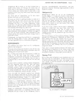
Fig. 40-System Contaminants
many difficulties in refrigerating systems, in most
instances it is the presence of moisture in the system that
accelerates these conditions. It can be said, therefore,
that moisture is the greatest problem of all. The acids
that it produces, in combination with both the metals
and the refrigerant, causes damaging corrosion. While
the corrosion may not form as rapidly with R-12 as with
some other refrigerants, the eventual formation is as
damaging.
If the operating pressure and temperature in the
evaporator is reduced to the freezing point, moisture in
the refrigerant can collect at the orifice of the expansion
valve and freeze. This temporarily restricts the flow of
liquid causing erratic cooling.
As previously mentioned, moisture in excess of the
desiccant’s capacity can cause it to powder.
Points to Remember
That the inside of the refrigerant system is completely
sealed from the outside world. If that seal remains
broken at any point—the system will soon be damaged.
That complete and positive sealing of the entire system
is vitally important and that this sealed condition is
absolutely necessary to retain the chemicals and keep
them in a pure and proper condition.
That all parts of the refrigerant system are under
pressure at all times, whether operating or idle, and that
any leakage points are continuously losing refrigerant
and oil.
That the leakage of refrigerant can be so silent that the
complete charge may be lost without warning.
That refrigerant gas is heavier than air and will rapidly
drop to the floor as it flows from a point of leakage.
That the pressure in the system may momentarily
become as high as 480 lbs. per square inch.
That the total refrigerant charge circulates through the
entire system at least once each minute.
That the compressor is continually giving up some
lubricating oil to the circulating refrigerant and depends
upon oil in the returning refrigerant for continuous
replenishment. Any stoppage or major loss of refrigerant
will therefore damage the compressor.
That the extreme internal dryness of a properly
processed system is a truly desert condition, with the
drying material in the receiver or accumulator holding
tightly onto the tiny droplets of residual moisture.
That the attraction of the drying material for moisture is
so powerful that if the receiver or accumulator is left
open, moisture will be drawn in from the outside air.
That water added to the refrigerant will start chemical
changes that can result in corrosion and eventual
breakdown of the chemicals in the system. Hydrochloric
acid is one result of an R-12 mixture with water.
That air in the refrigerant system may start reactions
that can cause malfunctions.
LIGHT DUTY TRUCK SERVICE MANUAL
Summary of Contents for Light Duty Truck 1973
Page 1: ......
Page 4: ......
Page 6: ......
Page 53: ...HEATER AND AIR CONDITIONING 1A 27 LIGHT DUTY TRUCK SERVICE MANUAL...
Page 115: ...LIGHT DUTY TRUCK SERVICE M A N U A L HEATER AND AIR CONDITIONING 1A 89...
Page 123: ...BODY 1B 3 Fig 6 Typical 06 Van LIGHT DUTY TRUCK SERVICE MANUAL...
Page 149: ...BODY 1B 29 Fig 84 Body Mounting 06 Fig 85 Body Mounting 14 LIGHT DUTY TRUCK SERVICE MANUAL...
Page 171: ...LIGHT DUTY TRUCK SERVICE M A N U A L Fig 2 Frame Horizontal Checking Typical FRAME 2 3...
Page 173: ...LIGHT DUTY TRUCK SERVICE M A N U A L Fig 4 10 30 Series Truck Frame FRAME 2 5...
Page 174: ...2 6 FRAME LIGHT DUTY TRUCK SERVICE MANUAL Fig 5 Underbody Reference Points G Van...
Page 185: ...FRONT SUSPENSION 3 11 Fig 16 Toe out on Turns LIGHT DUTY TRUCK SERVICE MANUAL...
Page 224: ......
Page 266: ......
Page 351: ...ENGINE 6 15 Fig ID Sectional View of Eight Cylinder Engine LIGHT DUTY TRUCK SERVICE MANUAL...
Page 375: ...EN G IN E 6 39 LIGHT DUTY TRUCK SERVICE MANUAL...
Page 376: ...6 4 0 ENGINE LIGHT DUTY TRUCK SERVICE MANUAL...
Page 377: ...ENG IN E 6 41 LIGHT DUTY TRUCK SERVICE MANUAL...
Page 378: ...LIGHT DUTY TRUCK SERVICE MANUAL Fig 37L K Series Engine Front Mount 6 42 ENG INE...
Page 400: ...6 6 4 ENG INE LIGHT DUTY TRUCK SERVICE MANUAL...
Page 401: ...ENG IN E 6 65 LIGHT DUTY TRUCK SERVICE MANUAL...
Page 402: ...6 6 6 ENGINE LIGHT DUTY TRUCK SERVICE MANUAL...
Page 403: ...E NG IN E 6 67 Fig 36V C Series Engine Mounts LIGHT DUTY TRUCK SERVICE MANUAL...
Page 410: ......
Page 423: ...EN G IN E C OOLING 6K 13 Fig 16 Overheating Chart LIGHT DUTY TRUCK SERVICE MANUAL...
Page 424: ...6 K 1 4 ENG INE COOLING Fig 17 Coolant Loss Chart LIGHT DUTY TRUCK SERVICE MANUAL...
Page 456: ...6M 32 ENGINE FUEL Fig K15 Accelerator Controls G Van L 6 LIGHT DUTY TRUCK SERVICE MANUAL...
Page 492: ......
Page 512: ...Fig 18e Vacuum Advance Diagram V8 Engine...
Page 516: ...6 T 2 4 E M IS S IO N CONTROL SYSTEMS LIGHT DUTY TRUCK SERVICE MANUAL...
Page 528: ......
Page 590: ......
Page 593: ...CLUTCHES MANUAL TRANSMISSIONS 7M 3 LIGHT DUTY TRUCK SERVICE MANUAL...
Page 598: ...7M 8 CLUTCHES MANUAL TRANSMISSIONS LIGHT DUTY TRUCK SERVICE MANUAL...
Page 642: ......
Page 654: ......
Page 743: ...FUEL TANKS AND EXHAUST 8 13 LIGHT DUTY TRUCK SERVICE MANUAL...
Page 744: ...8 14 FUEL TANKS AND EXHAUST LIGHT DUTY TRUCK SERVICE MANUAL...
Page 760: ...8 30 FUEL TANKS AND EXHAUST Fig 40 Exhaust Pipe P Models LIGHT DUTY TRUCK SERVICE MANUAL...
Page 761: ...FUEL TANKS AND EXHAUST 8 31 LIGHT DUTY TRUCK SERVICE MANUAL...
Page 763: ...FUEL TANKS AND EXHAUST 8 33 LIGHT DUTY TRUCK SERVICE MANUAL...
Page 766: ......
Page 832: ...LIGHT DUTY TRUCK SERVICE MANUAL Fig 106 Power Steering Pump Mounting Typical 9 66 STEERING...
Page 833: ...PUMP ASSEMBLY STEERING GEAR TYPICAL SMALL V8 TYPICAL LARGE V8 STEERING 9 67...
Page 861: ...STEERING 9 95 Fig 134 Power Steering Pump Leakage LIGHT DUTY TRUCK SERVICE MANUAL...
Page 864: ......
Page 876: ......
Page 886: ...11 10 CHASSIS SHEET METAL LIGHT DUTY TRUCK SERVICE MANUAL...
Page 891: ...ELECTRICAL BODY AND CHASSIS 12 5 LIGHT DUTY TRUCK SERVICE MANUAL...
Page 934: ......
Page 942: ......
Page 970: ......
Page 972: ......
Page 974: ......
Page 976: ...V...
Page 978: ......
Page 979: ......


