AUTOMATIC TRANSMISSION
CONTENTS OF THIS SECTION
SECTION 7A
Turbo Hydra-Matic 350 Transmission.................................... 7A-1
Turbo Hydra-Matic 400/475 Transmission........................... 7A-44
TURBO HYDRA-MATIC 3 5 0 TR A N SM ISS IO N
INDEX
General Description....................................................... 7A-1
Theory of Operation...................................................... 7A-2
Power Flow...................................................................... 7A-2
Hydraulic System - Functions of Valves and
Hydraulic Control U nits........................................ 7A-2
Hydraulic Oil System................................................... 7A-11
Maintenance and Adjustment..................................... 7A-28
Checking Transmission M ount.........................^...... 7A-28
Transmission Fluid....................................................... 7A-28
Manual Shift Linkage Check and Adjust
(C and P Models)........................................................... 7A-29
Manual and Control Linkage Adjustment
(G Model).................................................................... 7A-29
Detent Cable Adjustment........................................... 7A-30
Service Operations.......................................................... 7A-32
Transmission Replacement........................................ 7A-32
Other Service Operations.............................................. 7A-34
Governor........................................................................... 7A-34
Intermediate Clutch Accumulator............................ 7A-34
Diagnosis............................................................................. 7A-34
Sequence for Diagnosis............................................... 7A-34
Oil Checking Procedures............................................. 7A-35
Oil Leak Diagnosis....................................................... 7A-35
Oil Pressure Check........................................................ 7A-36
Case Porosity R epair................................................... 7A-36
Vacuum Modulator Diagnosis................................... 7A-36
Clutch Plate Diagnosis................................................ 7A-38
Causes of Burned Clutch Plates............................... 7A-38
Governor Pressure Check........................................... 7A-38
Manual Linkage............................................................. 7A-38
Road Test.......................................................................... 7A-38
Trouble Diagnosis............................................................ 7A-39
Diagnosis Chart.............................................................. 7A-39-43
Special Tools..................................................................... 7A-86
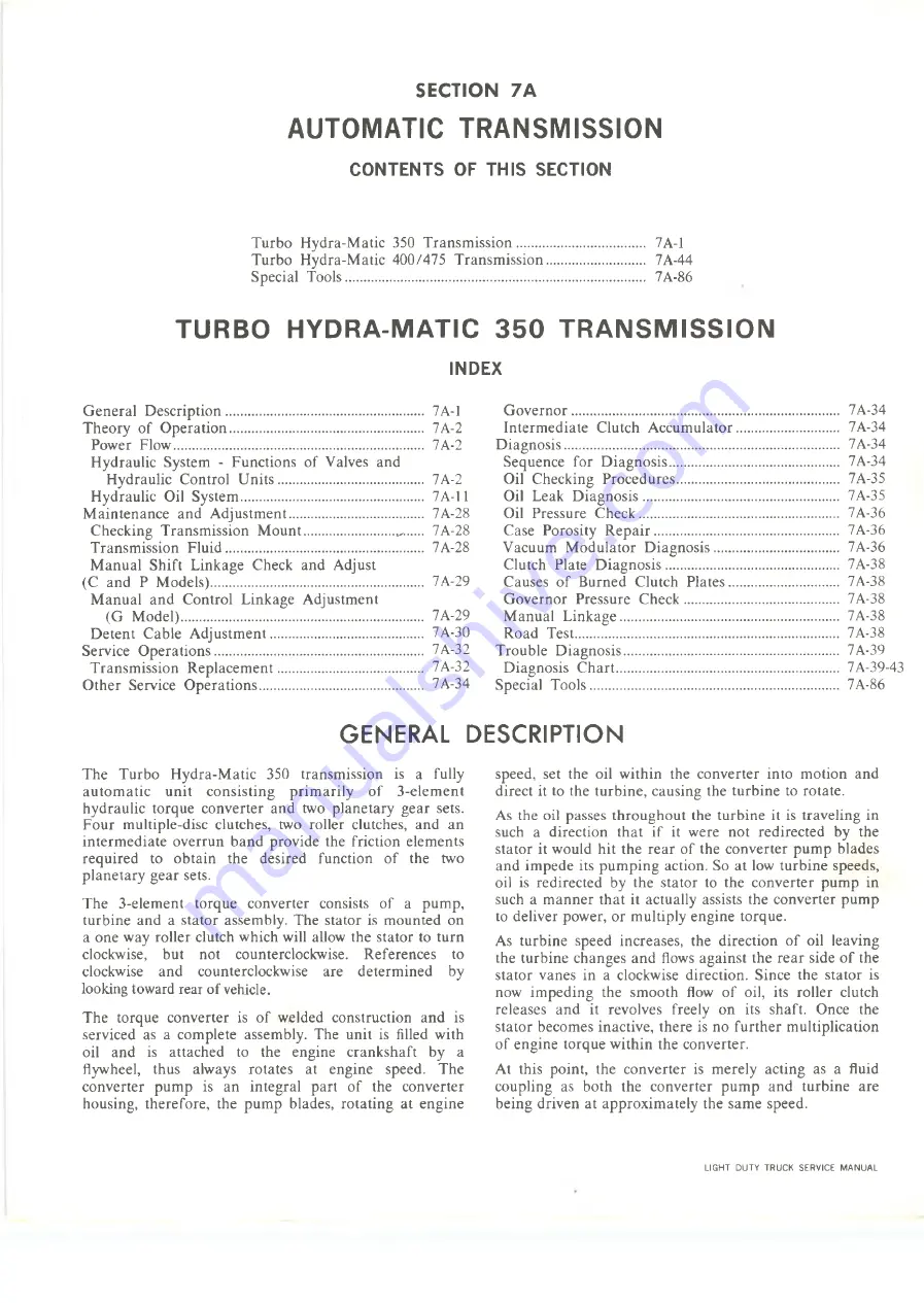
GENERAL DESCRIPTION
The Turbo Hydra-Matic 350 transmission is a fully
automatic unit consisting primarily of 3-element
hydraulic torque converter and two planetary gear sets.
Four multiple-disc clutches, two roller clutches, and an
intermediate overrun band provide the friction elements
required to obtain the desired function of the two
planetary gear sets.
The 3-element torque converter consists of a pump,
turbine and a stator assembly. The stator is mounted on
a one way roller clutch which will allow the stator to turn
clockwise, but not counterclockwise. References to
clockwise and counterclockwise are determined by
looking toward rear of vehicle.
The torque converter is of welded construction and is
serviced as a complete assembly. The unit is filled with
oil and is attached to the engine crankshaft by a
flywheel, thus always rotates at engine speed. The
converter pump is an integral part of the converter
housing, therefore, the pump blades, rotating at engine
speed, set the oil within the converter into motion and
direct it to the turbine, causing the turbine to rotate.
As the oil passes throughout the turbine it is traveling in
such a direction that if it were not redirected by the
stator it would hit the rear of the converter pump blades
and impede its pumping action. So at low turbine speeds,
oil is redirected by the stator to the converter pump in
such a manner that it actually assists the converter pump
to deliver power, or multiply engine torque.
As turbine speed increases, the direction of oil leaving
the turbine changes and flows against the rear side of the
stator vanes in a clockwise direction. Since the stator is
now impeding the smooth flow of oil, its roller clutch
releases and it revolves freely on its shaft. Once the
stator becomes inactive, there is no further multiplication
of engine torque within the converter.
At this point, the converter is merely acting as a fluid
coupling as both the converter pump and turbine are
being driven at approximately the same speed.
LIGHT DUTY TRUCK SERVICE MANUAL
Summary of Contents for Light Duty Truck 1973
Page 1: ......
Page 4: ......
Page 6: ......
Page 53: ...HEATER AND AIR CONDITIONING 1A 27 LIGHT DUTY TRUCK SERVICE MANUAL...
Page 115: ...LIGHT DUTY TRUCK SERVICE M A N U A L HEATER AND AIR CONDITIONING 1A 89...
Page 123: ...BODY 1B 3 Fig 6 Typical 06 Van LIGHT DUTY TRUCK SERVICE MANUAL...
Page 149: ...BODY 1B 29 Fig 84 Body Mounting 06 Fig 85 Body Mounting 14 LIGHT DUTY TRUCK SERVICE MANUAL...
Page 171: ...LIGHT DUTY TRUCK SERVICE M A N U A L Fig 2 Frame Horizontal Checking Typical FRAME 2 3...
Page 173: ...LIGHT DUTY TRUCK SERVICE M A N U A L Fig 4 10 30 Series Truck Frame FRAME 2 5...
Page 174: ...2 6 FRAME LIGHT DUTY TRUCK SERVICE MANUAL Fig 5 Underbody Reference Points G Van...
Page 185: ...FRONT SUSPENSION 3 11 Fig 16 Toe out on Turns LIGHT DUTY TRUCK SERVICE MANUAL...
Page 224: ......
Page 266: ......
Page 351: ...ENGINE 6 15 Fig ID Sectional View of Eight Cylinder Engine LIGHT DUTY TRUCK SERVICE MANUAL...
Page 375: ...EN G IN E 6 39 LIGHT DUTY TRUCK SERVICE MANUAL...
Page 376: ...6 4 0 ENGINE LIGHT DUTY TRUCK SERVICE MANUAL...
Page 377: ...ENG IN E 6 41 LIGHT DUTY TRUCK SERVICE MANUAL...
Page 378: ...LIGHT DUTY TRUCK SERVICE MANUAL Fig 37L K Series Engine Front Mount 6 42 ENG INE...
Page 400: ...6 6 4 ENG INE LIGHT DUTY TRUCK SERVICE MANUAL...
Page 401: ...ENG IN E 6 65 LIGHT DUTY TRUCK SERVICE MANUAL...
Page 402: ...6 6 6 ENGINE LIGHT DUTY TRUCK SERVICE MANUAL...
Page 403: ...E NG IN E 6 67 Fig 36V C Series Engine Mounts LIGHT DUTY TRUCK SERVICE MANUAL...
Page 410: ......
Page 423: ...EN G IN E C OOLING 6K 13 Fig 16 Overheating Chart LIGHT DUTY TRUCK SERVICE MANUAL...
Page 424: ...6 K 1 4 ENG INE COOLING Fig 17 Coolant Loss Chart LIGHT DUTY TRUCK SERVICE MANUAL...
Page 456: ...6M 32 ENGINE FUEL Fig K15 Accelerator Controls G Van L 6 LIGHT DUTY TRUCK SERVICE MANUAL...
Page 492: ......
Page 512: ...Fig 18e Vacuum Advance Diagram V8 Engine...
Page 516: ...6 T 2 4 E M IS S IO N CONTROL SYSTEMS LIGHT DUTY TRUCK SERVICE MANUAL...
Page 528: ......
Page 590: ......
Page 593: ...CLUTCHES MANUAL TRANSMISSIONS 7M 3 LIGHT DUTY TRUCK SERVICE MANUAL...
Page 598: ...7M 8 CLUTCHES MANUAL TRANSMISSIONS LIGHT DUTY TRUCK SERVICE MANUAL...
Page 642: ......
Page 654: ......
Page 743: ...FUEL TANKS AND EXHAUST 8 13 LIGHT DUTY TRUCK SERVICE MANUAL...
Page 744: ...8 14 FUEL TANKS AND EXHAUST LIGHT DUTY TRUCK SERVICE MANUAL...
Page 760: ...8 30 FUEL TANKS AND EXHAUST Fig 40 Exhaust Pipe P Models LIGHT DUTY TRUCK SERVICE MANUAL...
Page 761: ...FUEL TANKS AND EXHAUST 8 31 LIGHT DUTY TRUCK SERVICE MANUAL...
Page 763: ...FUEL TANKS AND EXHAUST 8 33 LIGHT DUTY TRUCK SERVICE MANUAL...
Page 766: ......
Page 832: ...LIGHT DUTY TRUCK SERVICE MANUAL Fig 106 Power Steering Pump Mounting Typical 9 66 STEERING...
Page 833: ...PUMP ASSEMBLY STEERING GEAR TYPICAL SMALL V8 TYPICAL LARGE V8 STEERING 9 67...
Page 861: ...STEERING 9 95 Fig 134 Power Steering Pump Leakage LIGHT DUTY TRUCK SERVICE MANUAL...
Page 864: ......
Page 876: ......
Page 886: ...11 10 CHASSIS SHEET METAL LIGHT DUTY TRUCK SERVICE MANUAL...
Page 891: ...ELECTRICAL BODY AND CHASSIS 12 5 LIGHT DUTY TRUCK SERVICE MANUAL...
Page 934: ......
Page 942: ......
Page 970: ......
Page 972: ......
Page 974: ......
Page 976: ...V...
Page 978: ......
Page 979: ......


