A U T O M A T IC T R A N S M IS S IO N
7 A -45
prevent the vehicle from rolling in either direction
(not on CL model). The engine may be started in
Park position.
R. REVERSE enables the vehicle to be operated in a
reverse direction.
N. Neutral postion enables the engine to be started
and run without driving the vehicle.
D. DRIVE Range is used for all normal driving
conditions and maximum economy. Drive Range
has three gear ratios, from the starting ratio to
direct drive. Detent downshifts are available by
depressing the accelerator to the floor.
L2. L2 Range has the same starting ration as Drive
Range, but prevents the transmission from shifting
ration when extra performance is desired. L2
Range can also be used for engine braking. L2
Range can be selected at any vehicle speed, and the
THEORY OF
MECHANICAL POWER FLOW
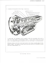
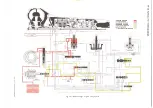
Refer to figures IT through 6T for related mechanical
power flow. Each figure explains what component is
applied or related in each stage of transmission
operation.
HYDRAULIC SYSTEM
FUNCTIONS OF
VALVES AND HYDRAULIC CONTROL UNITS
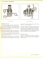
Pressure Control (Fig. 7T)
The transmission is automatically controlled by a
hydraulic system. Hydraulic pressure is supplied by the
transmission gear type oil pump, which is engine driven.
Main line pressure is controlled by a pressure regulator
valve train located in the pump. This regulator controls
line pressure automatically, in response to a pressure
signal from a modulator valve, in such a way that the
torque requirements of the transmission are met and
smooth shifts are obtained at all throttle openings.
To control line pressure properly, modulator pressure is
used which varies in the same manner as torque input to
the transmission. Since the converter torque output is the
product of engine torque and converter ratio, modulator
pressure must compensate for changes in either or both
of these.
To meet these requirements, modulator pressure is
regulated by engine vacuum which is an indicator of
engine torque and carburetor opening. It is decreased by
governor pressure with increase in vehicle speed because
converter torque ratio also decreases.
Pressure Regulator Valve (Fig. 7T)
1. Regulates line pressure according to a fixed spring
force and forces controlled by modulator and
reverse pressure.
transmission will shift to second gear and remain
in second until the vehicle speed or the throttle are
changed to obtain first gear operation in the same
manner as in D Range.
LI. LI Range can be selected at any vehicle speed, and
the transmission will shift to second gear and
remain in second until vehicle is reduced to
approximately 40 MPH, depending on axle ratio.
LI Range position prevents the transmission from
shifting out of first gear.
NOTE: It is very important that any
communication concerning the Turbo Hydra-
Matic 400/475 always contain the trans-
mision serial and vehicle identification
number.
OPERATION
2. Controls the flow of oil that charges the torque
converter, feeds the oil cooler and provides
lubrication for the transmission.
Vacuum Modulator Assembly (Fig. 8T)
The engine vacuum signal is provided by the vacuum
modulator, which consists of an evacuated metal bellows,
a diaphragm and two springs. These are so arranged that
when installed, the bellows and its external spring apply
a force which acts on the modulator valve. This force
acts on the modulator valve so that it increases
modulator pressure. Engine vacuum and the internal
spring act in the opposite direction to decrease
modulator, or low engine vacuum high modulator
pressure; high engine vacuum, and low modulator
pressure.
To reduce the effect of altitude on shift points, the
effective area of the diaphragm is made somewhat larger
than that of the bellows. Atmospheric pressure then acts
on the resulting differential area to reduce modulator
pressure.
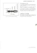
Governor Assembly (Fig. 9T)
The vehicle speed signal to the modulator valve is
supplied by the transmission governor, which is driven
by the output shaft. The governor consists of two
flyweights and a regulator valve. Centrifugal force of the
flyweights is imposed on the regulator valve causing it to
regulate a pressure signal that increases with speed.
To increase the accuracy of the governor signal at low
speeds, the flyweights are so designed that their effective
mass is greater at speeds below approximately 720 output
RPM than it is above this speed.
This is done by dividing each flyweight into two parts
and arranging them so that the primary weights act
through preloaded springs on the secondary weights,
LIGHT DUTY TRUCK SERVICE MANUAL
Summary of Contents for Light Duty Truck 1973
Page 1: ......
Page 4: ......
Page 6: ......
Page 53: ...HEATER AND AIR CONDITIONING 1A 27 LIGHT DUTY TRUCK SERVICE MANUAL...
Page 115: ...LIGHT DUTY TRUCK SERVICE M A N U A L HEATER AND AIR CONDITIONING 1A 89...
Page 123: ...BODY 1B 3 Fig 6 Typical 06 Van LIGHT DUTY TRUCK SERVICE MANUAL...
Page 149: ...BODY 1B 29 Fig 84 Body Mounting 06 Fig 85 Body Mounting 14 LIGHT DUTY TRUCK SERVICE MANUAL...
Page 171: ...LIGHT DUTY TRUCK SERVICE M A N U A L Fig 2 Frame Horizontal Checking Typical FRAME 2 3...
Page 173: ...LIGHT DUTY TRUCK SERVICE M A N U A L Fig 4 10 30 Series Truck Frame FRAME 2 5...
Page 174: ...2 6 FRAME LIGHT DUTY TRUCK SERVICE MANUAL Fig 5 Underbody Reference Points G Van...
Page 185: ...FRONT SUSPENSION 3 11 Fig 16 Toe out on Turns LIGHT DUTY TRUCK SERVICE MANUAL...
Page 224: ......
Page 266: ......
Page 351: ...ENGINE 6 15 Fig ID Sectional View of Eight Cylinder Engine LIGHT DUTY TRUCK SERVICE MANUAL...
Page 375: ...EN G IN E 6 39 LIGHT DUTY TRUCK SERVICE MANUAL...
Page 376: ...6 4 0 ENGINE LIGHT DUTY TRUCK SERVICE MANUAL...
Page 377: ...ENG IN E 6 41 LIGHT DUTY TRUCK SERVICE MANUAL...
Page 378: ...LIGHT DUTY TRUCK SERVICE MANUAL Fig 37L K Series Engine Front Mount 6 42 ENG INE...
Page 400: ...6 6 4 ENG INE LIGHT DUTY TRUCK SERVICE MANUAL...
Page 401: ...ENG IN E 6 65 LIGHT DUTY TRUCK SERVICE MANUAL...
Page 402: ...6 6 6 ENGINE LIGHT DUTY TRUCK SERVICE MANUAL...
Page 403: ...E NG IN E 6 67 Fig 36V C Series Engine Mounts LIGHT DUTY TRUCK SERVICE MANUAL...
Page 410: ......
Page 423: ...EN G IN E C OOLING 6K 13 Fig 16 Overheating Chart LIGHT DUTY TRUCK SERVICE MANUAL...
Page 424: ...6 K 1 4 ENG INE COOLING Fig 17 Coolant Loss Chart LIGHT DUTY TRUCK SERVICE MANUAL...
Page 456: ...6M 32 ENGINE FUEL Fig K15 Accelerator Controls G Van L 6 LIGHT DUTY TRUCK SERVICE MANUAL...
Page 492: ......
Page 512: ...Fig 18e Vacuum Advance Diagram V8 Engine...
Page 516: ...6 T 2 4 E M IS S IO N CONTROL SYSTEMS LIGHT DUTY TRUCK SERVICE MANUAL...
Page 528: ......
Page 590: ......
Page 593: ...CLUTCHES MANUAL TRANSMISSIONS 7M 3 LIGHT DUTY TRUCK SERVICE MANUAL...
Page 598: ...7M 8 CLUTCHES MANUAL TRANSMISSIONS LIGHT DUTY TRUCK SERVICE MANUAL...
Page 642: ......
Page 654: ......
Page 743: ...FUEL TANKS AND EXHAUST 8 13 LIGHT DUTY TRUCK SERVICE MANUAL...
Page 744: ...8 14 FUEL TANKS AND EXHAUST LIGHT DUTY TRUCK SERVICE MANUAL...
Page 760: ...8 30 FUEL TANKS AND EXHAUST Fig 40 Exhaust Pipe P Models LIGHT DUTY TRUCK SERVICE MANUAL...
Page 761: ...FUEL TANKS AND EXHAUST 8 31 LIGHT DUTY TRUCK SERVICE MANUAL...
Page 763: ...FUEL TANKS AND EXHAUST 8 33 LIGHT DUTY TRUCK SERVICE MANUAL...
Page 766: ......
Page 832: ...LIGHT DUTY TRUCK SERVICE MANUAL Fig 106 Power Steering Pump Mounting Typical 9 66 STEERING...
Page 833: ...PUMP ASSEMBLY STEERING GEAR TYPICAL SMALL V8 TYPICAL LARGE V8 STEERING 9 67...
Page 861: ...STEERING 9 95 Fig 134 Power Steering Pump Leakage LIGHT DUTY TRUCK SERVICE MANUAL...
Page 864: ......
Page 876: ......
Page 886: ...11 10 CHASSIS SHEET METAL LIGHT DUTY TRUCK SERVICE MANUAL...
Page 891: ...ELECTRICAL BODY AND CHASSIS 12 5 LIGHT DUTY TRUCK SERVICE MANUAL...
Page 934: ......
Page 942: ......
Page 970: ......
Page 972: ......
Page 974: ......
Page 976: ...V...
Page 978: ......
Page 979: ......


