STEER IN G
9 -9 3
isolate. For seepage leaks, the following method is
recommended.
A. With the vehicle’s engine off, wipe the complete
power steering system dry (gear, pump, hoses, and
connections).
B. Check oil level in pump’s reservoir and adjust as
directed in maintenance section.
C. Start engine and turn steering wheel from stop to
stop several times. Do not hold in corner for any
length of time as this can damage the power
steering pump. It is easier if someone else operates
the steering wheel while you search for the seepage.
D. Find the exact area of leakage.
E. Refer to the diagnostic chart to find the
recommended method of repair.
Quick Fixes
The purpose of this section is to acquaint you with the
types of leakage which can be repaired very easily. It
contains information on reservoir oil level, the hoses and
the hose connections.
An overfilled pump reservoir can be a cause for leakage
complaint. The oil in the steering system expands as
heated during normal usage. If overfilled the excess is
forced through the breather cap hole and may be
sprayed over the engine by air blast. Operate the engine
and steering system until normal operating temperature
is obtained. Remove the reservoir cap and check the
graduated level on the dipstick. Adjust the oil level as
required.
Seepage at the hose connections can be a cause for
leakage complaint and can be due to loose connection
nuts. If leakage is observed at the hose connections, and
the nut is not cross threaded, tighten the nuts at the gear
to 30 foot pounds.
The nut at the power steering pump should be tightened
to 40 foot pounds. If tightening to this torque does not
stop the leak, refer to the diagnostic chart.
If either the return hose or the pressure hose leaks,
replace the hose.
Component Replacement
Lip seals, which seal rotating shafts, require special
treatment. This type of seal is used on the steering gear
at the pitman shaft, at the stub shaft, and on the drive
shaft of the pump. When leakage occurs in one of these
areas, always replace the seal(s), after inspecting and
thoroughly cleaning the sealing surfaces. Replace the
shaft only if very severe pitting is found. If the corrosion
in the lip seal contact zone is slight, clean the surface of
the shaft with crocus cloth. Replace the shaft only if the
leakage cannot be stopped by smoothing with crocus
cloth first.
Housing or Cover Seepage - Both the power steering
gear and pump assemblies are leakage checked before
shipment. However, occasionally oil seepage may occur
from the gear or pump other than the seal areas. If this
type of leakage is found, replace the leaking part.
The following diagrams have been prepared to show the
potential areas of leakage. If leakage occurs in the zones
shown, replace the part listed using the service manual as
a guide.
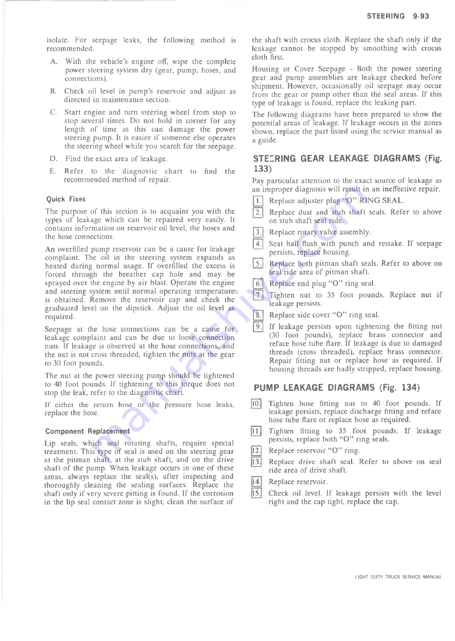
STEIRING GEAR LEAKAGE DIAGRAMS (Fig.
133)
Pay particular attention to the exact source of leakage as
an improper diagnosis will result in an ineffective repair.
[~T7|
Replace adjuster plug “O” RING SEAL.
[X] Replace dust and stub shaft seals. Refer to above
on stub shaft seal ride.
[~37| Replace rotary valve assembly.
[X] Seat ball flush with punch and restake. If seepage
persists, replace housing.
|~5~1 Replace both pitman shaft seals. Refer to above on
seal ride area of pitman shaft.
[~6~| Replace end plug “O” ring seal.
p7~| Tighten nut to 35 foot pounds. Replace nut if
leakage persists.
|T | Replace side cover “O” ring seal.
|~97|
If leakage persists upon tightening the fitting nut
(30 foot pounds), replace brass connector and
reface hose tube flare. If leakage is due to damaged
threads (cross threaded), replace brass connector.
Repair fitting nut or replace hose as required. If
housing threads are badly stripped, replace housing.
PUMP LEAKAGE DIAGRAMS (Fig. 134)
[lO~j Tighten hose fitting nut to 40 foot pounds. If
leakage persists, replace discharge fitting and reface
hose tube flare or replace hose as required.
Tighten fitting to 35 foot pounds. If leakage
persists, replace both “O” ring seals.
12. Replace reservoir “O” ring.
Replace drive shaft seal. Refer to above on seal
ride area of drive shaft.
Replace reservoir.
Check oil level. If leakage persists with the level
right and the cap tight, replace the cap.
11
LIGHT DUTY TRUCK SERVICE MANUAL
Summary of Contents for Light Duty Truck 1973
Page 1: ......
Page 4: ......
Page 6: ......
Page 53: ...HEATER AND AIR CONDITIONING 1A 27 LIGHT DUTY TRUCK SERVICE MANUAL...
Page 115: ...LIGHT DUTY TRUCK SERVICE M A N U A L HEATER AND AIR CONDITIONING 1A 89...
Page 123: ...BODY 1B 3 Fig 6 Typical 06 Van LIGHT DUTY TRUCK SERVICE MANUAL...
Page 149: ...BODY 1B 29 Fig 84 Body Mounting 06 Fig 85 Body Mounting 14 LIGHT DUTY TRUCK SERVICE MANUAL...
Page 171: ...LIGHT DUTY TRUCK SERVICE M A N U A L Fig 2 Frame Horizontal Checking Typical FRAME 2 3...
Page 173: ...LIGHT DUTY TRUCK SERVICE M A N U A L Fig 4 10 30 Series Truck Frame FRAME 2 5...
Page 174: ...2 6 FRAME LIGHT DUTY TRUCK SERVICE MANUAL Fig 5 Underbody Reference Points G Van...
Page 185: ...FRONT SUSPENSION 3 11 Fig 16 Toe out on Turns LIGHT DUTY TRUCK SERVICE MANUAL...
Page 224: ......
Page 266: ......
Page 351: ...ENGINE 6 15 Fig ID Sectional View of Eight Cylinder Engine LIGHT DUTY TRUCK SERVICE MANUAL...
Page 375: ...EN G IN E 6 39 LIGHT DUTY TRUCK SERVICE MANUAL...
Page 376: ...6 4 0 ENGINE LIGHT DUTY TRUCK SERVICE MANUAL...
Page 377: ...ENG IN E 6 41 LIGHT DUTY TRUCK SERVICE MANUAL...
Page 378: ...LIGHT DUTY TRUCK SERVICE MANUAL Fig 37L K Series Engine Front Mount 6 42 ENG INE...
Page 400: ...6 6 4 ENG INE LIGHT DUTY TRUCK SERVICE MANUAL...
Page 401: ...ENG IN E 6 65 LIGHT DUTY TRUCK SERVICE MANUAL...
Page 402: ...6 6 6 ENGINE LIGHT DUTY TRUCK SERVICE MANUAL...
Page 403: ...E NG IN E 6 67 Fig 36V C Series Engine Mounts LIGHT DUTY TRUCK SERVICE MANUAL...
Page 410: ......
Page 423: ...EN G IN E C OOLING 6K 13 Fig 16 Overheating Chart LIGHT DUTY TRUCK SERVICE MANUAL...
Page 424: ...6 K 1 4 ENG INE COOLING Fig 17 Coolant Loss Chart LIGHT DUTY TRUCK SERVICE MANUAL...
Page 456: ...6M 32 ENGINE FUEL Fig K15 Accelerator Controls G Van L 6 LIGHT DUTY TRUCK SERVICE MANUAL...
Page 492: ......
Page 512: ...Fig 18e Vacuum Advance Diagram V8 Engine...
Page 516: ...6 T 2 4 E M IS S IO N CONTROL SYSTEMS LIGHT DUTY TRUCK SERVICE MANUAL...
Page 528: ......
Page 590: ......
Page 593: ...CLUTCHES MANUAL TRANSMISSIONS 7M 3 LIGHT DUTY TRUCK SERVICE MANUAL...
Page 598: ...7M 8 CLUTCHES MANUAL TRANSMISSIONS LIGHT DUTY TRUCK SERVICE MANUAL...
Page 642: ......
Page 654: ......
Page 743: ...FUEL TANKS AND EXHAUST 8 13 LIGHT DUTY TRUCK SERVICE MANUAL...
Page 744: ...8 14 FUEL TANKS AND EXHAUST LIGHT DUTY TRUCK SERVICE MANUAL...
Page 760: ...8 30 FUEL TANKS AND EXHAUST Fig 40 Exhaust Pipe P Models LIGHT DUTY TRUCK SERVICE MANUAL...
Page 761: ...FUEL TANKS AND EXHAUST 8 31 LIGHT DUTY TRUCK SERVICE MANUAL...
Page 763: ...FUEL TANKS AND EXHAUST 8 33 LIGHT DUTY TRUCK SERVICE MANUAL...
Page 766: ......
Page 832: ...LIGHT DUTY TRUCK SERVICE MANUAL Fig 106 Power Steering Pump Mounting Typical 9 66 STEERING...
Page 833: ...PUMP ASSEMBLY STEERING GEAR TYPICAL SMALL V8 TYPICAL LARGE V8 STEERING 9 67...
Page 861: ...STEERING 9 95 Fig 134 Power Steering Pump Leakage LIGHT DUTY TRUCK SERVICE MANUAL...
Page 864: ......
Page 876: ......
Page 886: ...11 10 CHASSIS SHEET METAL LIGHT DUTY TRUCK SERVICE MANUAL...
Page 891: ...ELECTRICAL BODY AND CHASSIS 12 5 LIGHT DUTY TRUCK SERVICE MANUAL...
Page 934: ......
Page 942: ......
Page 970: ......
Page 972: ......
Page 974: ......
Page 976: ...V...
Page 978: ......
Page 979: ......


