E N G I N E
6 - 3 5
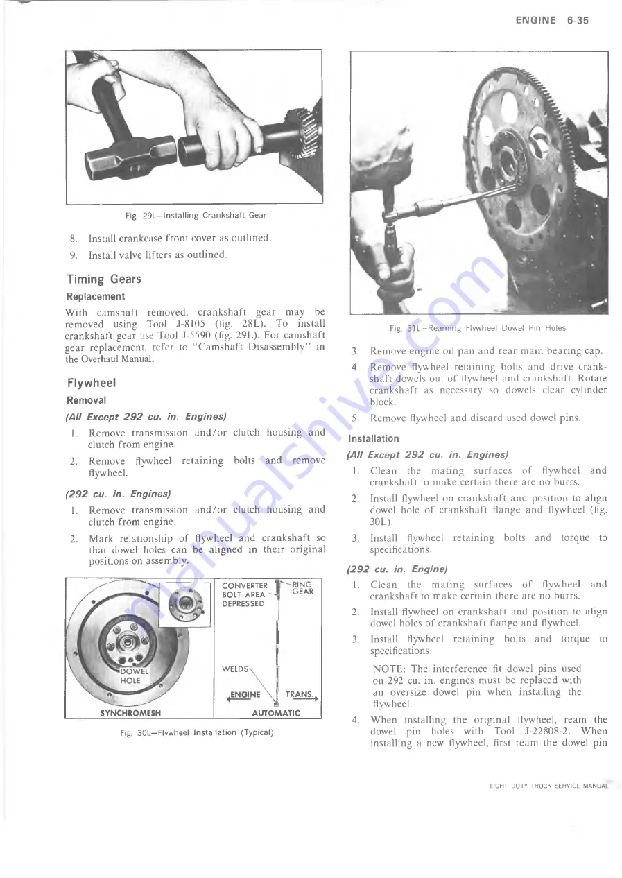
Fig. 29L—Installing Crankshaft Gear
8. Install crankcase front cover as outlined.
9. Install valve lifters as outlined.
Timing Gears
Replacement
With camshaft removed, crankshaft gear may be
removed using Tool J-8105 (fig. 28L). To install
crankshaft gear use Tool J-5590 (fig. 29L). For camshaft
gear replacement, refer to “Camshaft Disassembly” in
the Overhaul Manual.
Flywheel
Removal
(All Except 2 9 2 cu. in. Engines)
1. Remove transmission and/or clutch housing and
clutch from engine.
2. Remove flywheel retaining bolts and remove
flywheel.
(2 9 2 cu. in. Engines)
1. Remove transmission and/or clutch housing and
clutch from engine.
2. Mark relationship of flywheel and crankshaft so
that dowel holes can be aligned in their original
positions on assembly.
Fig. 30L—Flywheel Installation (Typical)
Fig. 31L—Reaming Flywheel Dowel Pin Holes
3. Remove engine oil pan and rear main bearing cap.
4. Remove flywheel retaining bolts and drive crank
shaft dowels out of flywheel and crankshaft. Rotate
crankshaft as necessary so dowels clear cylinder
block.
5. Remove flywheel and discard used dowel pins.
Installation
(All Except 2 9 2 cu. in. Engines)
1. Clean the mating surfaces of flywheel and
crankshaft to make certain there are no burrs.
2. Install flywheel on crankshaft and position to align
dowel hole of crankshaft flange and flywheel (fig.
30L).
3. Install flywheel retaining bolts and torque to
specifications.
(2 9 2 cu. in. Engine)
1. Clean the mating surfaces of flywheel and
crankshaft to make certain there are no burrs.
2. Install flywheel on crankshaft and position to align
dowel holes of crankshaft flange and flywheel.
3. Install flywheel retaining bolts and torque to
specifications.
NOTE: The interference fit dowel pins used
on 292 cu. in. engines must be replaced with
an oversize dowel pin when installing the
flywheel.
4. When installing the original flywheel, ream the
dowel pin holes with Tool J-22808-2. When
installing a new flywheel, first ream the dowel pin
SYNCHROMESH
CONVERTER
BOLT AREA - J |
GEAR
DEPRESSED
WELDS
TRANS.^
AUTOMATIC
LIGHT DUTY TRUCK SERVICE MANUAL
Summary of Contents for Light Duty Truck 1973
Page 1: ......
Page 4: ......
Page 6: ......
Page 53: ...HEATER AND AIR CONDITIONING 1A 27 LIGHT DUTY TRUCK SERVICE MANUAL...
Page 115: ...LIGHT DUTY TRUCK SERVICE M A N U A L HEATER AND AIR CONDITIONING 1A 89...
Page 123: ...BODY 1B 3 Fig 6 Typical 06 Van LIGHT DUTY TRUCK SERVICE MANUAL...
Page 149: ...BODY 1B 29 Fig 84 Body Mounting 06 Fig 85 Body Mounting 14 LIGHT DUTY TRUCK SERVICE MANUAL...
Page 171: ...LIGHT DUTY TRUCK SERVICE M A N U A L Fig 2 Frame Horizontal Checking Typical FRAME 2 3...
Page 173: ...LIGHT DUTY TRUCK SERVICE M A N U A L Fig 4 10 30 Series Truck Frame FRAME 2 5...
Page 174: ...2 6 FRAME LIGHT DUTY TRUCK SERVICE MANUAL Fig 5 Underbody Reference Points G Van...
Page 185: ...FRONT SUSPENSION 3 11 Fig 16 Toe out on Turns LIGHT DUTY TRUCK SERVICE MANUAL...
Page 224: ......
Page 266: ......
Page 351: ...ENGINE 6 15 Fig ID Sectional View of Eight Cylinder Engine LIGHT DUTY TRUCK SERVICE MANUAL...
Page 375: ...EN G IN E 6 39 LIGHT DUTY TRUCK SERVICE MANUAL...
Page 376: ...6 4 0 ENGINE LIGHT DUTY TRUCK SERVICE MANUAL...
Page 377: ...ENG IN E 6 41 LIGHT DUTY TRUCK SERVICE MANUAL...
Page 378: ...LIGHT DUTY TRUCK SERVICE MANUAL Fig 37L K Series Engine Front Mount 6 42 ENG INE...
Page 400: ...6 6 4 ENG INE LIGHT DUTY TRUCK SERVICE MANUAL...
Page 401: ...ENG IN E 6 65 LIGHT DUTY TRUCK SERVICE MANUAL...
Page 402: ...6 6 6 ENGINE LIGHT DUTY TRUCK SERVICE MANUAL...
Page 403: ...E NG IN E 6 67 Fig 36V C Series Engine Mounts LIGHT DUTY TRUCK SERVICE MANUAL...
Page 410: ......
Page 423: ...EN G IN E C OOLING 6K 13 Fig 16 Overheating Chart LIGHT DUTY TRUCK SERVICE MANUAL...
Page 424: ...6 K 1 4 ENG INE COOLING Fig 17 Coolant Loss Chart LIGHT DUTY TRUCK SERVICE MANUAL...
Page 456: ...6M 32 ENGINE FUEL Fig K15 Accelerator Controls G Van L 6 LIGHT DUTY TRUCK SERVICE MANUAL...
Page 492: ......
Page 512: ...Fig 18e Vacuum Advance Diagram V8 Engine...
Page 516: ...6 T 2 4 E M IS S IO N CONTROL SYSTEMS LIGHT DUTY TRUCK SERVICE MANUAL...
Page 528: ......
Page 590: ......
Page 593: ...CLUTCHES MANUAL TRANSMISSIONS 7M 3 LIGHT DUTY TRUCK SERVICE MANUAL...
Page 598: ...7M 8 CLUTCHES MANUAL TRANSMISSIONS LIGHT DUTY TRUCK SERVICE MANUAL...
Page 642: ......
Page 654: ......
Page 743: ...FUEL TANKS AND EXHAUST 8 13 LIGHT DUTY TRUCK SERVICE MANUAL...
Page 744: ...8 14 FUEL TANKS AND EXHAUST LIGHT DUTY TRUCK SERVICE MANUAL...
Page 760: ...8 30 FUEL TANKS AND EXHAUST Fig 40 Exhaust Pipe P Models LIGHT DUTY TRUCK SERVICE MANUAL...
Page 761: ...FUEL TANKS AND EXHAUST 8 31 LIGHT DUTY TRUCK SERVICE MANUAL...
Page 763: ...FUEL TANKS AND EXHAUST 8 33 LIGHT DUTY TRUCK SERVICE MANUAL...
Page 766: ......
Page 832: ...LIGHT DUTY TRUCK SERVICE MANUAL Fig 106 Power Steering Pump Mounting Typical 9 66 STEERING...
Page 833: ...PUMP ASSEMBLY STEERING GEAR TYPICAL SMALL V8 TYPICAL LARGE V8 STEERING 9 67...
Page 861: ...STEERING 9 95 Fig 134 Power Steering Pump Leakage LIGHT DUTY TRUCK SERVICE MANUAL...
Page 864: ......
Page 876: ......
Page 886: ...11 10 CHASSIS SHEET METAL LIGHT DUTY TRUCK SERVICE MANUAL...
Page 891: ...ELECTRICAL BODY AND CHASSIS 12 5 LIGHT DUTY TRUCK SERVICE MANUAL...
Page 934: ......
Page 942: ......
Page 970: ......
Page 972: ......
Page 974: ......
Page 976: ...V...
Page 978: ......
Page 979: ......


