E N G IN E ELECTRICAL
6 Y -33
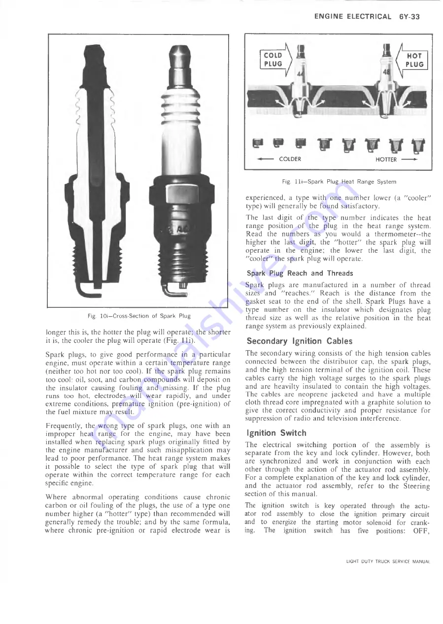
Fig. lO i—C ro s s -S e c tio n of S p a r k Plu g
longer this is, the hotter the plug will operate; the shorter
it is, the cooler the plug will operate (Fig. 1 li).
Spark plugs, to give good performance in a particular
engine, must operate within a certain temperature range
(neither too hot nor too cool). If the spark plug remains
too cool: oil, soot, and carbon compounds will deposit on
the insulator causing fouling and missing. If the plug
runs too hot, electrodes will wear rapidly, and under
extreme conditions, premature ignition (pre-ignition) of
the fuel mixture may result.
Frequently, the wrong type of spark plugs, one with an
improper heat range for the engine, may have been
installed when replacing spark plugs originally fitted by
the engine manufacturer and such misapplication may
lead to poor performance. The heat range system makes
it possible to select the type of spark plug that will
operate within the correct temperature range for each
specific engine.
Where abnormal operating conditions cause chronic
carbon or oil fouling of the plugs, the use of a type one
number higher (a "hotter" type) than recommended will
generally remedy the trouble; and by the same formula,
where chronic pre-ignition or rapid electrode wear is
------- COLDER
HOTTER ------- ►
Fig. l l i — S p a r k P lu g H e a t R a n g e S y s te m
experienced, a type with one number lower (a "cooler"
type) will generally be found satisfactory.
The last digit of the type number indicates the heat
range position of the plug in the heat range system.
Read the numbers as you would a thermometer-the
higher the last digit, the "hotter" the spark plug will
operate in the engine; the lower the last digit, the
"cooler" the spark plug will operate.
Spark Plug Reach and Threads
Spark plugs are manufactured in a number of thread
sizes and "reaches." Reach is the distance from the
gasket seat to the end of the shell. Spark Plugs have a
type number on the insulator which designates plug
thread size as well as the relative position in the heat
range system as previously explained.
Secondary Ignition Cables
The secondary wiring consists of the high tension cables
connected between the distributor cap, the spark plugs,
and the high tension terminal of the ignition coil. These
cables carry the high voltage surges to the spark plugs
and are heavilty insulated to contain the high voltages.
The cables are neoprene jacketed and have a multiple
cloth thread core impregnated with a graphite solution to
give the correct conductivity and proper resistance for
suppression of radio and television interference.
Ignition Switch
The electrical switching portion of the assembly is
separate from the key and lock cylinder. However, both
are synchronized and work in conjunction with each
other through the action of the actuator rod assembly.
For a complete explanation of the key and lock cylinder,
and the actuator rod assembly, refer to the Steering
section of this manual.
The ignition switch is key operated through the actu
ator rod assembly to close the ignition primary circuit
and to energize the starting motor solenoid for crank
ing. The ignition switch has five positions: OFF,
LIGHT DUTY TRUCK SERVICE MANUAL
Summary of Contents for Light Duty Truck 1973
Page 1: ......
Page 4: ......
Page 6: ......
Page 53: ...HEATER AND AIR CONDITIONING 1A 27 LIGHT DUTY TRUCK SERVICE MANUAL...
Page 115: ...LIGHT DUTY TRUCK SERVICE M A N U A L HEATER AND AIR CONDITIONING 1A 89...
Page 123: ...BODY 1B 3 Fig 6 Typical 06 Van LIGHT DUTY TRUCK SERVICE MANUAL...
Page 149: ...BODY 1B 29 Fig 84 Body Mounting 06 Fig 85 Body Mounting 14 LIGHT DUTY TRUCK SERVICE MANUAL...
Page 171: ...LIGHT DUTY TRUCK SERVICE M A N U A L Fig 2 Frame Horizontal Checking Typical FRAME 2 3...
Page 173: ...LIGHT DUTY TRUCK SERVICE M A N U A L Fig 4 10 30 Series Truck Frame FRAME 2 5...
Page 174: ...2 6 FRAME LIGHT DUTY TRUCK SERVICE MANUAL Fig 5 Underbody Reference Points G Van...
Page 185: ...FRONT SUSPENSION 3 11 Fig 16 Toe out on Turns LIGHT DUTY TRUCK SERVICE MANUAL...
Page 224: ......
Page 266: ......
Page 351: ...ENGINE 6 15 Fig ID Sectional View of Eight Cylinder Engine LIGHT DUTY TRUCK SERVICE MANUAL...
Page 375: ...EN G IN E 6 39 LIGHT DUTY TRUCK SERVICE MANUAL...
Page 376: ...6 4 0 ENGINE LIGHT DUTY TRUCK SERVICE MANUAL...
Page 377: ...ENG IN E 6 41 LIGHT DUTY TRUCK SERVICE MANUAL...
Page 378: ...LIGHT DUTY TRUCK SERVICE MANUAL Fig 37L K Series Engine Front Mount 6 42 ENG INE...
Page 400: ...6 6 4 ENG INE LIGHT DUTY TRUCK SERVICE MANUAL...
Page 401: ...ENG IN E 6 65 LIGHT DUTY TRUCK SERVICE MANUAL...
Page 402: ...6 6 6 ENGINE LIGHT DUTY TRUCK SERVICE MANUAL...
Page 403: ...E NG IN E 6 67 Fig 36V C Series Engine Mounts LIGHT DUTY TRUCK SERVICE MANUAL...
Page 410: ......
Page 423: ...EN G IN E C OOLING 6K 13 Fig 16 Overheating Chart LIGHT DUTY TRUCK SERVICE MANUAL...
Page 424: ...6 K 1 4 ENG INE COOLING Fig 17 Coolant Loss Chart LIGHT DUTY TRUCK SERVICE MANUAL...
Page 456: ...6M 32 ENGINE FUEL Fig K15 Accelerator Controls G Van L 6 LIGHT DUTY TRUCK SERVICE MANUAL...
Page 492: ......
Page 512: ...Fig 18e Vacuum Advance Diagram V8 Engine...
Page 516: ...6 T 2 4 E M IS S IO N CONTROL SYSTEMS LIGHT DUTY TRUCK SERVICE MANUAL...
Page 528: ......
Page 590: ......
Page 593: ...CLUTCHES MANUAL TRANSMISSIONS 7M 3 LIGHT DUTY TRUCK SERVICE MANUAL...
Page 598: ...7M 8 CLUTCHES MANUAL TRANSMISSIONS LIGHT DUTY TRUCK SERVICE MANUAL...
Page 642: ......
Page 654: ......
Page 743: ...FUEL TANKS AND EXHAUST 8 13 LIGHT DUTY TRUCK SERVICE MANUAL...
Page 744: ...8 14 FUEL TANKS AND EXHAUST LIGHT DUTY TRUCK SERVICE MANUAL...
Page 760: ...8 30 FUEL TANKS AND EXHAUST Fig 40 Exhaust Pipe P Models LIGHT DUTY TRUCK SERVICE MANUAL...
Page 761: ...FUEL TANKS AND EXHAUST 8 31 LIGHT DUTY TRUCK SERVICE MANUAL...
Page 763: ...FUEL TANKS AND EXHAUST 8 33 LIGHT DUTY TRUCK SERVICE MANUAL...
Page 766: ......
Page 832: ...LIGHT DUTY TRUCK SERVICE MANUAL Fig 106 Power Steering Pump Mounting Typical 9 66 STEERING...
Page 833: ...PUMP ASSEMBLY STEERING GEAR TYPICAL SMALL V8 TYPICAL LARGE V8 STEERING 9 67...
Page 861: ...STEERING 9 95 Fig 134 Power Steering Pump Leakage LIGHT DUTY TRUCK SERVICE MANUAL...
Page 864: ......
Page 876: ......
Page 886: ...11 10 CHASSIS SHEET METAL LIGHT DUTY TRUCK SERVICE MANUAL...
Page 891: ...ELECTRICAL BODY AND CHASSIS 12 5 LIGHT DUTY TRUCK SERVICE MANUAL...
Page 934: ......
Page 942: ......
Page 970: ......
Page 972: ......
Page 974: ......
Page 976: ...V...
Page 978: ......
Page 979: ......

