1 1 -8 CHASSIS SHEET M ETAL
F R O N T FENDER A N D S K IR T (FIG S. 9 A N D
1 0 )
Removal
1. Remove hood and hood hinge assembly.
2. Disconnect and remove battery (right side or
auxiliary left side).
3. Remove head lamp bezel, wiring and attachments
from fender.
4. Remove screws attaching upper and lower radiator
grille panels.
5. Remove screws attaching skirt to radiator support.
6. Remove two (2) top rear fender bolts and shims.
7. Remove bolt and shims at bottom of fender.
8. Remove bolt and shim(s) attaching skirt to
underbody.
9. Remove two (2) screw attaching support bracket to
fender.
10. Remove five (5) screws attaching radiator support
to front fender.
11. Lift fender and skirt from truck.
Installation
Install front fender and skirt assembly in reverse order
of removal.
F R O N T FENDER S K IR T
Refer to figure 9 for removal and installation of Front
Fender Skirt.
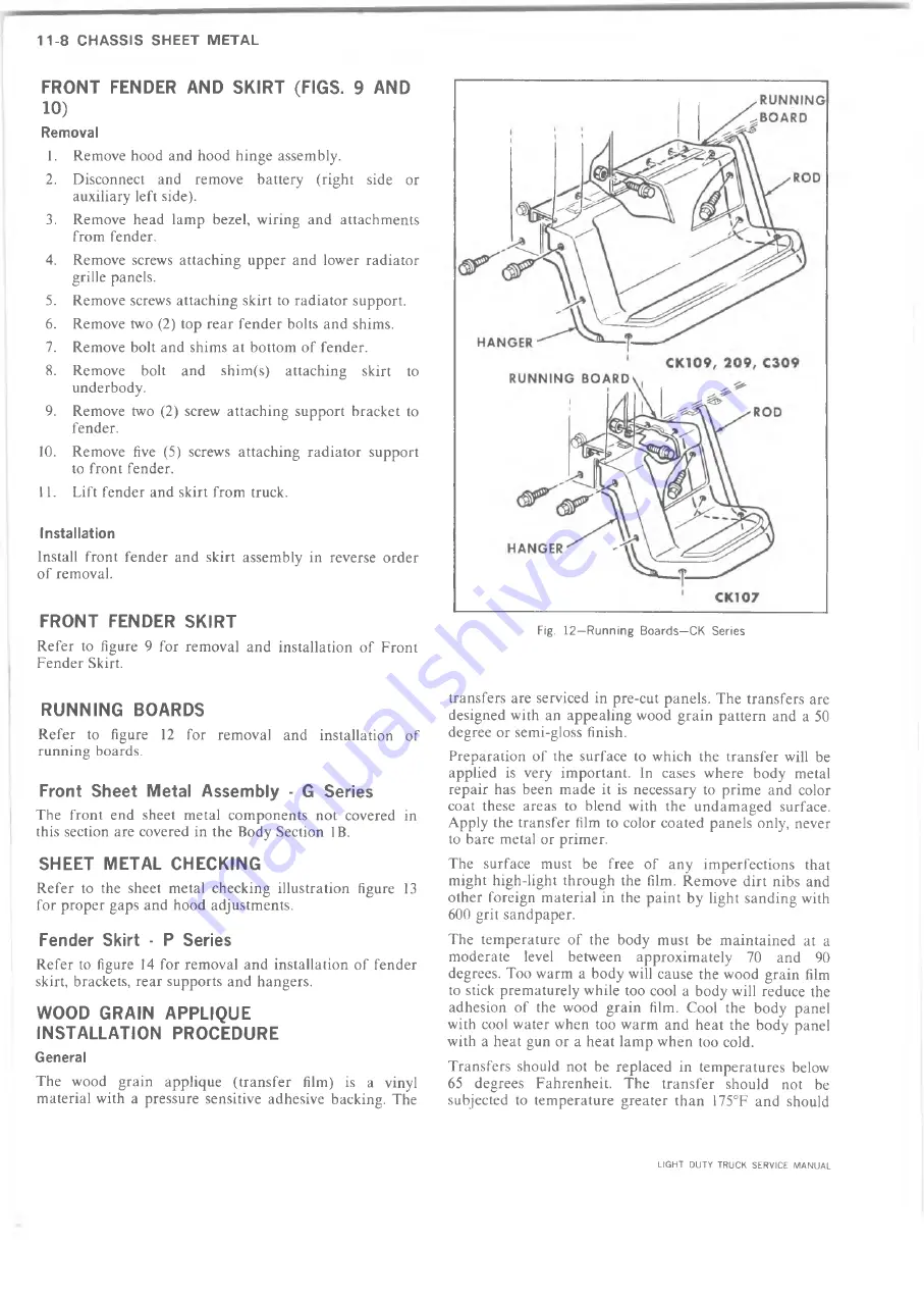
R U N N IN G BOARDS
Refer to figure 12 for removal and installation of
running boards.
Front S heet M etal A ssem bly - G Series
The front end sheet metal components not covered in
this section are covered in the Body Section IB.
SHEET M E TA L C H E C K IN G
Refer to the sheet metal checking illustration figure 13
for proper gaps and hood adjustments.
Fender Skirt - P Series
Refer to figure 14 for removal and installation of fender
skirt, brackets, rear supports and hangers.
W O O D G R A IN A P P LIQ U E
IN S T A L L A T IO N PR O C ED U R E
General
The wood grain applique (transfer film) is a vinyl
material with a pressure sensitive adhesive backing. The
Fig. 12—Running Boards—CK Series
transfers are serviced in pre-cut panels. The transfers are
designed with an appealing wood grain pattern and a 50
degree or semi-gloss finish.
Preparation of the surface to which the transfer will be
applied is very important. In cases where body metal
repair has been made it is necessary to prime and color
coat these areas to blend with the undamaged surface.
Apply the transfer film to color coated panels only, never
to bare metal or primer.
The surface must be free of any imperfections that
might high-light through the film. Remove dirt nibs and
other foreign material in the paint by light sanding with
600 grit sandpaper.
The temperature of the body must be maintained at a
moderate level between approximately 70 and 90
degrees. Too warm a body will cause the wood grain film
to stick prematurely while too cool a body will reduce the
adhesion of the wood grain film. Cool the body panel
with cool water when too warm and heat the body panel
with a heat gun or a heat lamp when too cold.
Transfers should not be replaced in temperatures below
65 degrees Fahrenheit. The transfer should not be
subjected to temperature greater than 175°F and should
LIGHT DUTY TRUCK SERVICE MANUAL
Summary of Contents for Light Duty Truck 1973
Page 1: ......
Page 4: ......
Page 6: ......
Page 53: ...HEATER AND AIR CONDITIONING 1A 27 LIGHT DUTY TRUCK SERVICE MANUAL...
Page 115: ...LIGHT DUTY TRUCK SERVICE M A N U A L HEATER AND AIR CONDITIONING 1A 89...
Page 123: ...BODY 1B 3 Fig 6 Typical 06 Van LIGHT DUTY TRUCK SERVICE MANUAL...
Page 149: ...BODY 1B 29 Fig 84 Body Mounting 06 Fig 85 Body Mounting 14 LIGHT DUTY TRUCK SERVICE MANUAL...
Page 171: ...LIGHT DUTY TRUCK SERVICE M A N U A L Fig 2 Frame Horizontal Checking Typical FRAME 2 3...
Page 173: ...LIGHT DUTY TRUCK SERVICE M A N U A L Fig 4 10 30 Series Truck Frame FRAME 2 5...
Page 174: ...2 6 FRAME LIGHT DUTY TRUCK SERVICE MANUAL Fig 5 Underbody Reference Points G Van...
Page 185: ...FRONT SUSPENSION 3 11 Fig 16 Toe out on Turns LIGHT DUTY TRUCK SERVICE MANUAL...
Page 224: ......
Page 266: ......
Page 351: ...ENGINE 6 15 Fig ID Sectional View of Eight Cylinder Engine LIGHT DUTY TRUCK SERVICE MANUAL...
Page 375: ...EN G IN E 6 39 LIGHT DUTY TRUCK SERVICE MANUAL...
Page 376: ...6 4 0 ENGINE LIGHT DUTY TRUCK SERVICE MANUAL...
Page 377: ...ENG IN E 6 41 LIGHT DUTY TRUCK SERVICE MANUAL...
Page 378: ...LIGHT DUTY TRUCK SERVICE MANUAL Fig 37L K Series Engine Front Mount 6 42 ENG INE...
Page 400: ...6 6 4 ENG INE LIGHT DUTY TRUCK SERVICE MANUAL...
Page 401: ...ENG IN E 6 65 LIGHT DUTY TRUCK SERVICE MANUAL...
Page 402: ...6 6 6 ENGINE LIGHT DUTY TRUCK SERVICE MANUAL...
Page 403: ...E NG IN E 6 67 Fig 36V C Series Engine Mounts LIGHT DUTY TRUCK SERVICE MANUAL...
Page 410: ......
Page 423: ...EN G IN E C OOLING 6K 13 Fig 16 Overheating Chart LIGHT DUTY TRUCK SERVICE MANUAL...
Page 424: ...6 K 1 4 ENG INE COOLING Fig 17 Coolant Loss Chart LIGHT DUTY TRUCK SERVICE MANUAL...
Page 456: ...6M 32 ENGINE FUEL Fig K15 Accelerator Controls G Van L 6 LIGHT DUTY TRUCK SERVICE MANUAL...
Page 492: ......
Page 512: ...Fig 18e Vacuum Advance Diagram V8 Engine...
Page 516: ...6 T 2 4 E M IS S IO N CONTROL SYSTEMS LIGHT DUTY TRUCK SERVICE MANUAL...
Page 528: ......
Page 590: ......
Page 593: ...CLUTCHES MANUAL TRANSMISSIONS 7M 3 LIGHT DUTY TRUCK SERVICE MANUAL...
Page 598: ...7M 8 CLUTCHES MANUAL TRANSMISSIONS LIGHT DUTY TRUCK SERVICE MANUAL...
Page 642: ......
Page 654: ......
Page 743: ...FUEL TANKS AND EXHAUST 8 13 LIGHT DUTY TRUCK SERVICE MANUAL...
Page 744: ...8 14 FUEL TANKS AND EXHAUST LIGHT DUTY TRUCK SERVICE MANUAL...
Page 760: ...8 30 FUEL TANKS AND EXHAUST Fig 40 Exhaust Pipe P Models LIGHT DUTY TRUCK SERVICE MANUAL...
Page 761: ...FUEL TANKS AND EXHAUST 8 31 LIGHT DUTY TRUCK SERVICE MANUAL...
Page 763: ...FUEL TANKS AND EXHAUST 8 33 LIGHT DUTY TRUCK SERVICE MANUAL...
Page 766: ......
Page 832: ...LIGHT DUTY TRUCK SERVICE MANUAL Fig 106 Power Steering Pump Mounting Typical 9 66 STEERING...
Page 833: ...PUMP ASSEMBLY STEERING GEAR TYPICAL SMALL V8 TYPICAL LARGE V8 STEERING 9 67...
Page 861: ...STEERING 9 95 Fig 134 Power Steering Pump Leakage LIGHT DUTY TRUCK SERVICE MANUAL...
Page 864: ......
Page 876: ......
Page 886: ...11 10 CHASSIS SHEET METAL LIGHT DUTY TRUCK SERVICE MANUAL...
Page 891: ...ELECTRICAL BODY AND CHASSIS 12 5 LIGHT DUTY TRUCK SERVICE MANUAL...
Page 934: ......
Page 942: ......
Page 970: ......
Page 972: ......
Page 974: ......
Page 976: ...V...
Page 978: ......
Page 979: ......


