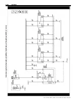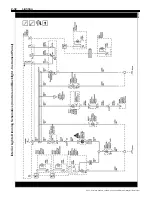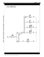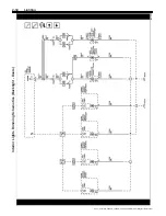
Lighting
2-37
Description and Operation
Exterior Lighting Systems
Description and Operation
The exterior lighting system consist of the following
lamps:
•
Backup lamps
•
Front fog lamps
•
Hazard warning lamps
•
Headlamps
•
Park, tail, license, and marker lamps
•
Stop lamps
•
Turn signal lamps
•
Trailer lighting
Low Beam Headlamps
The headlamps may be turned ON in 3 different ways:
•
When the headlamp switch is placed in the ON
position, for normal operation
•
When the headlamp switch is placed in the AUTO
position, for automatic lamp control
•
When the headlamp switch is placed in the AUTO
position, with the windshield wipers ON in daylight
conditions, after a 6 second delay
The BCM will also command the low beam headlamps
ON during daylight conditions when the following
conditions are met:
•
Headlamp switch in the AUTO position
•
Windshield wipers ON
•
Vehicle in any gear but PARK
When the BCM commands the low beam headlamps
ON, the vehicle operator will notice the interior
backlighting for the instrument cluster and the various
switches with backlighting control will dim to the level of
brightness selected by the instrument panel dimmer
switch.
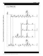
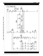
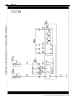
The body control module (BCM) monitors three signal
circuits from the headlamp switch. When the headlamp
switch is in the AUTO position, all three signal circuits
are open. When placed in the AUTO position, the BCM
monitors inputs from the ambient light sensor to
determine if headlamps are required or if daytime
running lamps will be activated based on outside
lighting conditions. When the headlamp switch is
placed in the OFF position, the headlamp switch
headlamps OFF signal circuit is grounded, indicating to
the BCM that the exterior lamps should be turned OFF.
With the headlamp switch in the PARK position, the
headlamp switch park lamps ON signal circuit is
grounded, indicating that the park lamps have been
requested. When the headlamp switch is placed in the
HEADLAMP position, both the headlamp switch park
lamps ON signal circuit and the headlamp switch
headlamps ON signal circuit are grounded. The BCM
responds to the inputs by illuminating the park lamps
and headlamps. When the low beam headlamps are
requested, the BCM applies B+ to both low beam
headlamp control circuits illuminating the low beam
headlamps.
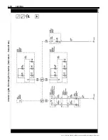
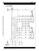
High Beam Headlamps
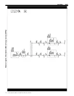
When the low beam headlamps are ON and the turn
signal/multifunction switch is placed in the high beam
position, ground is applied to the BCM through the high
beam signal circuit. The BCM responds to the high
beam request by applying ground to the high beam
relay control circuit which energizes the high beam
relay. With the high beam relay energized, the switch
contacts close allowing battery voltage to flow through
the 3 pin high beam fuse to the high beam control
circuits illuminating the left and right high beam
headlamps.
Flash to Pass
When the turn signal/multifunction switch is
momentarily placed in the flash to pass position,
ground is applied to the turn signal/multifunction switch.
The turn signal/multifunction switch applies ground to
the body control module (BCM) through the flash to
pass switch signal circuit. The BCM responds to the
flash to pass request by applying ground to the high
beam relay control circuit. This energizes the high
beam relay, closing the switch side contacts of the high
beam relay, applying battery voltage to the 3 pin high
beam fuse. Battery voltage is applied from the high
beam fuse through the high beam control circuit to the
high beam headlamp assemblies. This causes the high
beam headlamps to illuminate at full brightness
momentarily.
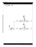
Front Fog Lamps
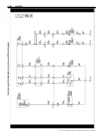
The front fog lamp relay is supplied with battery voltage
at all times. The front fog lamp switch signal circuit is
grounded momentarily by pressing the front fog lamp
switch. The body control module (BCM) energizes the
front fog lamp relay by applying ground to the front fog
lamp relay control circuit. When the front fog lamp relay
is energized, the relay switch contacts close and
battery voltage is applied through the front fog lamp
fuse to the front fog lamp supply voltage circuit which
illuminates the front fog lamps.
Hazard Lamps
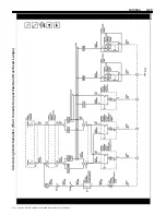
The hazard flashers may be activated in any power
mode. The hazard switch signal circuit is momentarily
grounded when the hazard switch is pressed. The body
control module (BCM) responds to the hazard switch
signal input by supplying battery voltage to all four turn
signal lamps in an ON and OFF duty cycle. When the
hazard switch is activated, the BCM sends a serial data
message to the instrument panel cluster requesting
both turn signal indicators to be cycled ON and OFF.
The instrument panel dimmer switch controls the
brightness of the interior backlighting components.
When the instrument panel dimmer switch is placed in
a desired brightness position, the body control module
(BCM) receives a signal from the instrument panel
dimmer switch and responds by applying a pulse width
modulated voltage to the hazard switch light emitting
diode (LED) backlighting control circuit illuminating the
LED to the desired level of brightness.
2021 - Silverado 4500HD, 5500HD, and 6500HD Electrical Body Builder Manual

