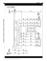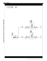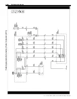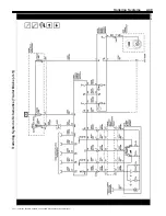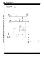
Trailering Systems
2-51
Description and Operation
Trailering Description and Operation
Trailer Lighting
The K9 Body Control Module (BCM) is responsible for
all trailer lighting. Anytime the BCM commands an
exterior lighting system on, the BCM will also command
the same trailer lighting system on regardless if a trailer
is connected or not.
Backup Lamps
For trailer backup lamp operation, the trailer backup
lamps relay is supplied with battery voltage at all times.
With the engine running and the transmission in the
reverse position, the transmission control module
(TCM) sends a serial data message to the body control
module (BCM). The message indicates that the gear
selector is in the reverse position. The BCM responds
to the backup lamp request by energizing the trailer
backup lamps relay by applying battery voltage to the
trailer backup lamps relay control circuit. When the
trailer backup lamps relay is energized, the relay switch
contacts close and battery voltage is applied through
the backup lamp fuse to the trailer backup lamps
control circuit which illuminates the trailer backup
lamps. Once the driver moves the gear selector out of
the reverse position, a message is sent by the TCM
via serial data requesting the BCM to remove battery
voltage from the trailer backup lamps relay control
circuit.
Park Lamps
For trailer park lamp operation, the trailer park lamps
relay is supplied with battery voltage at all times. When
the headlamp switch is placed in the HEAD or PARK
position, ground is applied to the park lamp switch ON
signal circuit to the body control module (BCM). The
BCM responds to the park lamp request by energizing
the park lamps relay by applying ground to the trailer
park lamps relay control circuit. When the trailer park
lamps relay is energized, the relay switch contacts
close and battery voltage is applied through the trailer
parks lamp fuse to the trailer park lamp control circuit
which illuminates the trailer park lamps.
Stop Lamps
For trailer stop lamp operation, the left and right trailer
stop/turn signal lamp relay
’
s are supplied with battery
voltage at all times. The brake pedal position sensor is
used to sense the action of the driver application of the
brake pedal. When the variable signal reaches a
voltage threshold indicating the brakes have been
applied, the BCM energizes the left and right trailer
stop/turn signal lamp relay
’
s by applying ground to the
left and right trailer stop/turn signal lamp relay control
circuits. With the left and right trailer stop/turn signal
lamp relay
’
s energized, the relay switch contacts close
and battery voltage is applied through the left and right
trailer stop/turn signal fuse
’
s to the trailer stop lamp
control circuits which illuminates the trailer stop lamps.
Turn Signal Lamps
For trailer turn signal lamp operation, the left and right
trailer stop/turn signal lamp relay
’
s are supplied with
battery voltage at all times. Ground is applied at all
times to the turn signal/multifunction switch. The turn
signal lamps may only be activated with the ignition
switch in the ON or START positions. When the turn
signal/multifunction switch is placed in either the TURN
RIGHT or TURN LEFT position, ground is applied to the
body control module (BCM) through either the right turn
or left turn signal switch signal circuit. The BCM
responds to the turn signal switch input by applying
pulsating ground to the left and right trailer stop/turn
signal lamp relay control circuits energizing the relay
’
s
in an ON and OFF cycle. With the left and right trailer
stop/turn signal lamp relay
’
s energized, the relay switch
contacts cycle ON and OFF applying battery voltage
through the left and right trailer stop/turn signal fuse
’
s to
the trailer turn signal lamp control circuits which
illuminates the trailer turn signal lamps in an ON and
OFF cycle.
Trailer Battery Charging System
Trailer battery charging is accomplished through
constant battery voltage from the X50A Fuse Block
–
Underhood to the X88 Trailer Connector. Battery
voltage is supplied to terminal E at the X88 Trailer
Connector at all times. If equipped, the trailer battery
will constantly be charged by the vehicle
’
s electrical
system anytime the trailer is connected. Some trailers
require the B+ circuit to the X88 Trailer Connector for
the trailer brakes to function.
Trailer Brakes
A trailer brake control system is used to control the
amount of trailer braking power that is made available
to trailers with brakes that require a controlled electrical
output signal for actuation.
The power output to the trailer brakes is based on both
the amount of braking being applied by the vehicle
’
s
brake system and on the type of trailer brakes detected.
The Trailer Brake Control System is compatible with
two types of Trailer Brake Systems as listed below:
1.
Electric Brakes
A controlled electrical output
signal energizes an electric-magnet/lever arm
assembly that directly actuates the brake
mechanism. The GDS name for this system is
“
Electromagnetic Brakes
”
.
2.
Electric Over Hydraulic Brakes
A controlled
electrical output signal energizes a remote, trailer
mounted hydraulic pump to build brake pressure in
a closed hydraulic system on the trailer. The
hydraulic fluid pressure actuates the brake
mechanism. The GDS name for this system is
“
Electrohydraulic Brakes
”
.
Trailer Brake Output Versus Trailer Brake Type
•
The trailer brake system characterizes the trailer
brakes as either Electric Brake or Electric Over
Hydraulic Brake automatically. This
characterization may be affected by the number,
type, and age of the trailer brake magnets, as well
as any other devices installed on the trailer brakes
(i.e. adapters for Electric Over Hydraulic brake
functionality).
•
The trailer brake system is fully operational with
either characterization.
•
Some features of the trailer brake system may be
different based on the trailer brake type
characterization. An example of this is at zero
2021 - Silverado 4500HD, 5500HD, and 6500HD Electrical Body Builder Manual

