2-52
Trailering Systems
speed, where pressing the service brake pedal will
produce output when the trailer brakes are
characterized as Electric Brakes, but not when
characterized as Electric Over Hydraulic Brakes.
•
Sliding the manual trailer brake apply lever will
produce output at zero speed for either
characterization.
The user gain allows the driver to adjust the amount of
trailer brake output to match the trailer load and road
surface. The controller determines the desired trailer
brake output and provides a control signal to the
K133 Trailer Brake Power Control Module. The
K133 Trailer Brake Power Control Module amplifies the
signal and provides the output required to activate the
Electric or Electric Over Hydraulic trailer brakes.
The trailer brake control can support up to a maximum
of four axles with electric trailer brakes (8 brake
magnets).
Connecting a trailer that is not compatible with the
trailer brake system may result in reduced or complete
loss of trailer braking. There may be an increase in
stopping distance or trailer instability which could result
in personal injury or damage to the vehicle, trailer or
other property. An aftermarket controller may be
available for use with trailers with surge or air trailer
brake systems.
To determine the type of brakes on your trailer and the
availability of controllers, check with your trailer
manufacturer or dealer. Do not power up an aftermarket
controller with the factory brake controller at the
same time.
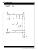
The vehicle is equipped with the following trailer
braking components:
•
K38A Chassis Control Module-Auxiliary
•
K133 Trailer Brake Power Control Module
•
S76 Trailer Brake Control Panel
•
Manual Trailer Brake Apply
•
Trailer Gain Adjustment
•
Trailer Brake Driver Information Center Display
Chassis Control Module-Auxiliary
The K38A Chassis Control Module-Auxiliary is a
serviceable GMLAN module. The chassis control
module sends the low power commanded duty cycle
signal to the trailer brake power control module. The
trailer brake power control module amplifies the signal
and provides an output that is required to drive the
trailer brakes.
Trailer Brake Power Control Module
The K133 Trailer Brake Power Control Module (TBPM)
is a solid state power switching module that supplies
power to the trailer brakes at the input command duty
cycle. Diagnostic messages are sent from the TBPM to
the CCM on a dedicated LIN bus.
Trailer Brake Control Panel
The S76 Trailer Brake Control Panel contains the trailer
gain and manual apply switches. It is located on the
instrument panel to the left of the steering column.
Refer to the instrument panel overview for more
information on the location. The control panel and
switches allows you to adjust the amount of output,
referred to as trailer gain, available to the Electric or
Electric Over Hydraulic brakes. It also allows you to
manually apply the trailer brakes. The trailer brake
control panel and switches are used along with the
trailer brake display page on the driver information
center to adjust and display power output to the trailer
brakes.
Manual Trailer Brake Apply
The manual trailer brake apply lever is located on the
S76 Trailer Brake Control Panel and is used to apply
the trailer
’
s Electric or Electric Over Hydraulic brakes
independent of the vehicle
’
s brakes. This lever is used
in the trailer gain adjustment procedure to properly
adjust the power output to the trailer brakes.
Sliding the lever to the left will apply only the trailer
brakes. The power output to the trailer is indicated in
the trailer brake display page in the Driver Information
Center (DIC). If the vehicle
’
s service brakes are applied
while using the manual trailer brake apply lever, the
trailer output power will be the greater of the two.
The trailer and the vehicle
’
s brake lamps will come on
when either the vehicle
’
s braking or manual trailer
brakes are applied.
Trailer Gain Adjustment
Trailer gain should be set for a specific trailering
condition and must be adjusted any time vehicle
loading, trailer loading or road surface conditions
change. It is important to re-adjust trailer gain any time
the tow vehicle, trailer loading or road surface
conditions change or it you notice trailer wheel lock-up
at any time while you are towing.
Setting the trailer gain properly is needed for the best
trailer stopping performance. A trailer that is
over-gained may result in locked trailer brakes. A trailer
that is under-gained may result in not enough trailer
braking. Both of these conditions may result in poor
stopping and stability of the vehicle and trailer.
Trailer Gain Adjustment Procedure
•
Adjust trailer gain in 0.5 step increments up to 10
gain setting by using the gain adju/
−
buttons on the trailer brake control panel switch.
Pressing and holding a gain button will cause the
trailer gain to continuously increment or
decrement. To turn the output to the trailer off, set
the gain to zero.
•
Drive the tow vehicle and trailer combination on a
level surface representative of the towing
condition and free of traffic at approximately 32
–
40 km/h (20
–
25 mph) and fully apply the manual
trailer brake apply lever mechanism located on the
trailer brake control panel switch. Adjusting the
trailer gain at slower speeds may result in an
incorrect gain setting.
•
Adjust the trailer gain to just below the threshold of
trailer wheel lock-up . Trailer wheel lock-up may
not occur if towing a heavily loaded trailer. In this
case, adjust the trailer gain to the highest
allowable setting for the towing condition.
Hill Start Assist
The hill start assist allows the driver to launch the
vehicle without a roll back when the driver is moving
their foot from the brake pedal to the accelerator pedal.
2021 - Silverado 4500HD, 5500HD, and 6500HD Electrical Body Builder Manual

