background image

Page 6

SKU 41983

for technical questions, please call 1-800-444-3353.

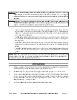
Vibration Hazard

This tool vibrates during use.  Repeated or long-term exposure to vibration may 
cause temporary or permanent physical injury, particularly to the hands, arms and 
shoulders.  To reduce the risk of vibration-related injury:

Anyone  using  vibrating  tools  regularly  or  for  an  extended  period  should  first  be 

1. 

examined by a doctor and then have regular medical check-ups to ensure medical 
problems are not being caused or worsened from use.  Pregnant women or people 
who have impaired blood circulation to the hand, past hand injuries, nervous system 
disorders, diabetes, or Raynaud’s Disease should not use this tool.  If you feel any 
medical or physical symptoms related to vibration (such as tingling, numbness, and 
white or blue fingers), seek medical advice as soon as possible.

Do not smoke during use.  Nicotine reduces the blood supply to the hands and 

2. 

fingers, increasing the risk of vibration-related injury.

Wear suitable gloves to reduce the vibration effects on the user.

3. 

Use tools with the lowest vibration when there is a choice between different pro-

4. 

cesses.

Include vibration-free periods each day of work.

5. 

Grip tool as lightly as possible (while still keeping safe control of it).  Let the tool do 

6. 

the work.

To reduce vibration, maintain the tool as explained in this manual.  If any abnormal 

7. 

vibration occurs, stop use immediately.

gROunDing

improperly connecting the grounding wire can result in electric 
shock.

check  with  a  qualified  electrician  if  you  are  in  doubt  as  to 
whether the outlet is properly grounded.  Do not modify the 
power  cord  plug  provided  with  the  tool.    never  remove  the 
grounding prong from the plug.  Do not use the tool if the power 
cord or plug is damaged.    if damaged,  have  it  repaired  by a 
service facility before use.  if the plug will not fit the outlet, have 
a proper outlet installed by a qualified electrician.

WARNING

REV 07j

Summary of Contents for 41983

Page 1: ...our website at http www harborfreight com To prevent serious injury read and understand all warnings and instructions before use Copyright 2000 by Harbor Freight Tools All rights reserved No portion...

Page 2: ...ber Keep this manual and invoice in a safe and dry place for future reference GENERAL SAFETY RULES WARNING READ AND UNDERSTAND ALL INSTRUCTIONS Failure to follow all instructions listed below may resu...

Page 3: ...ed Power Cords increase the risk of electric shock When operating a power tool outside use an outdoor extension cord marked W A 6 or W These extension cords are rated for outdoor use and reduce the ri...

Page 4: ...s Do not use until repaired Check for misalignment or binding of moving parts breakage of parts and any other 7 condition that may affect the tool s operation If damaged have the tool serviced before...

Page 5: ...tion people with pacemakers should adhere to the following Avoid operating power tools alone Don t use a power tool with the power switch locked on If powered via a power cord be certain that the tool...

Page 6: ...ring use Nicotine reduces the blood supply to the hands and 2 fingers increasing the risk of vibration related injury Wear suitable gloves to reduce the vibration effects on the user 3 Use tools with...

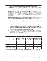
Page 7: ...ords with inadequately sized wire causes a seri ous drop in voltage resulting in loss of power and possible tool damage See Table A The smaller the gauge number of the wire the greater the capacity of...

Page 8: ...8 14 12 10 12 1 16 0 14 12 10 16 1 20 0 12 10 TABLE A Based on limiting the line voltage drop to five volts at 150 of the rated amperes Symbology Double Insulated V Volts Alternating Current Canadian...

Page 9: ...bits become very hot in use Do not remove drill bits until the bit has completely cooled off Do not strike stuck bits with a hammer as metal chips may fly off Always remove the electrical plug from th...

Page 10: ...unterclockwise 1 Once the Auxiliary Handle 107 is sufficiently loose pull back on the Handle Holder 108 2 until the hole in the Handle Holder 108 is fully open Main Handle Left Side Position Main Hand...

Page 11: ...See Figure 2 To Hammer Drill set the Switching Knob 22 so that the Hammer and Drill are facing forward Turn the Main Handle 91 so that it points to the left at the Hammer and Drill symbol To Chisel se...

Page 12: ...bon Brushes 5 Using a small standard screwdriver remove the Brush Covers 81 When you remove a the Brush Caps the Carbon Brush Holder 83 may spring out Do not lose the Carbon Brushes If the Brush Holde...

Page 13: ...90 days from the date of purchase This warranty does not apply to damage due directly or indirectly to misuse abuse negligence or accidents repairs or alterations outside our facilities criminal acti...

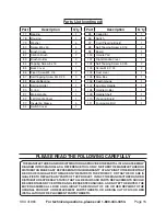
Page 14: ...0 Screw M5 x 25 4 31 Spring 4 32 Cylinder Case 1 33 Cylinder Cap 1 34 Oil Seal 1 35 Washer 1 36 Bearing 1 37 Distance Ring 1 38 Distance Cover 1 Part Description Q ty 39 Front Cover 1 40 O ring 1 41 S...

Page 15: ...s or her repairs to the original product or replacement parts thereto or arising out of his or her installation of replacement parts thereto Parts List continued Part Description Q ty 77 Bearing 1 78...

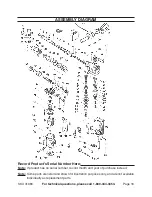
Page 16: ...4 3353 ASSEMBLY DIAGRAM Record Product s Serial Number Here Note If product has no serial number record month and year of purchase instead Note Some parts are listed and shown for illustration purpose...

Page 17: ...produit d crit ici Distribu exclusivement par le Harbor Freight Tools 3491 Mission Oaks Blvd Camarillo CA 93011 Visitez notre site Internet http www harborfreight com Lire ce mat riau avant le fait d...

Page 18: ...pouvoir le consulter l avenir REGLES DE SECURITE Avertissement Lisez et assurez vous de bien comprendre toutes les instructions Le non respect des instructions ci apr s peut entrainer un risque de ch...

Page 19: ...avec les surfaces reli es la terre telles que 3 tuyaux radiateurs cuisini res et r frig rateurs Le risque de choc lectrique est accru lorsque le corps est mis la terre N exposez pas les outils lectriq...

Page 20: ...uv e par ANSI UTILISATION ET ENTRETIEN DE L OUTIL Utilisez des serre joints pas fournis ou un autre moyen pratique de retenir 1 et de soutenir la pi ce travailler sur une plate forme stable Le fait de...

Page 21: ...s non autoris ou le non respect des consignes d entretien peut entra ner des risques de choc lectrique ou de blessures Hasard de Vibration Cet instrument vibre pendant l utilisation Le contact r p t o...

Page 22: ...raissent sur votre 3 outil Des informations importantes y paraissent S il manque de l information ou si les informations sont mal crites communiquez avec Harbor Freight Tools pour faire remplacer l ou...

Page 23: ...uis retirez la fiche de la prise avant de sortir AVERTISSEMENT 13 Certains outils tels que les sableuses lectriques les scies les meules les perceuses ou certains autres outils de construction peuvent...

Page 24: ...es Inc de L Association Canadienne de Normalisation et du Code Electrique Natio nal Voir L IMAGE B Les outils double isolation peuvent tre utilis 2 dans l un ou l autre de la prise de courant d un cir...

Page 25: ...contact avec des objets tranchants tre expos e 8 de la chaleur excessive ni tre utilis e dans un endroit mouill ou humide CALIBRE MINIMUM DES RALLONGES Courant de 120 ou 240 V seulement L INTENSIT NO...

Page 26: ...teur 96 Voir L IMAGE 1 au dessus pour vous familiariser avec les caract ristiques divers de la marteau rotatif Une liste compl te de num ro de la pi ce figure la page 9 Le Sch ma du Produit complet se...

Page 27: ...Auxiliaire 107 dans le sens des aiguilles d une montre pour desserrer la bande et La boulon quatre perpendiculaire 111 Une fois desserr e tournez la Manche Auxiliaire la position d sir Pour serrer tou...

Page 28: ...ge du Marteau et de la Perceuse soit tourn e vers l avant Tournez La Poign e Sup rieure 91 pour qu elle tourn vers le droit au symbole de la perceuse Voir L Image 2 Pour percer avec le marteau fix L I...

Page 29: ...t de d bris LUBRICATION Utilisez la cl anglaise dans cette trousse de desserrer Le Capu 4 chon Plomb 18 situ au dessus du bo tier Ajut l huile inclus dans cette trousse et remplacez et serrez Le Capuc...

Page 30: ...r 2 Changez la bobine lectrique 3 Remplacez la bobine de stator 4 Remplacez Les Balai de Carbone 5 L outil semble faire trop de bruit ne tourne pas ou tourne lentement Moteur surcharg la suite de la p...

Page 31: ...sse 1 34 Bague d Etanch it d huile 1 35 Rondelle d Etanch it 1 36 Al sage 1 37 Bague Entretoise 1 38 Couvercle Distance 1 39 Couvercle l avant 1 Pi ce Description Q ty 40 Joint Torique 1 41 Ressort 1...

Page 32: ...LA RESPONSABILIT SURVENANT DU FAIT DE SES R PARATIONS AU PRODUIT ORIGINAL OU AUX PI CES D TACH ES Y OU SURVENANT DU FAIT DE SON INSTALLATION DE PI CES D TACH ES Y LES PI CES Pi ce Description Q ty 79...

Page 33: ...a t 1 800 444 3353 SCH MA DU PRODUIT Notez le Num ro de S rie du Produit ici Remarque S il n y a pas de num ro de s rie notez la date d achat Remarque Des pi ces figurant sur la liste ont pour but d i...

Reviews: