background image

Page 10

For technical questions, please call 1-888-866-5797.

Item 64056 


Sa
FE
ty

Op
E

ra
ti

O

n

Maint

E

nanc

E

S

E

tup

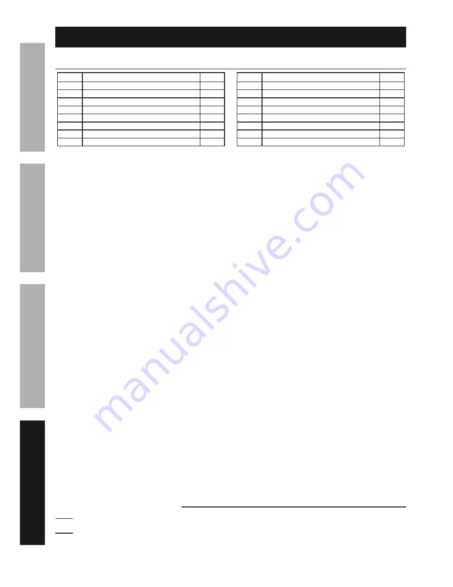
parts List and Diagram

parts List

part

Description

Qty

1

Soldering Tip

3

2

Soldering Tip Nut

2

3

Heat Insulator

1

4

Transformer Assembly

1

5

Right Housing

1

6

Plate

2

7

Left Housing

1

8

Screw

4

part

Description

Qty

9

Power Cord

1

10

Power Cord Sleeve

1

11

Heat Shrink Tubing

1

12

Terminal

2

13

Trigger

1

14

Button

1

15

LED

1

16

Back Cover

1

record product’s Serial number Here: 
note:

 If product has no serial number, record month and year of purchase instead.

note:

 Some parts are listed and shown for illustration purposes only, 

and are not available individually as replacement parts.

Summary of Contents for 64056

Page 1: ...ference 18i When unpacking make sure that the product is intact and undamaged If any parts are missing or broken please call 1 888 866 5797 as soon as possible Copyright 2017 by Harbor Freight Tools A...

Page 2: ...on which if not avoided could result in minor or moderate injury Addresses practices not related to personal injury iMpOrtant SaFEty inFOrMatiOn General power tool Safety Warnings read all safety warn...

Page 3: ...rgizing power tools that have the Trigger on invites accidents 4 Do not overreach Keep proper footing and balance at all times This enables better control of the power tool in unexpected situations 5...

Page 4: ...sease Ulcers Damage to the reproductive organs Inflammation of the small intestine or stomach Kidney damage Respiratory diseases such as emphysema bronchitis or pneumonia 5 Keep head out of fumes Do n...

Page 5: ...rom the supply outlet increases you must use a heavier gauge extension cord Using extension cords with inadequately sized wire causes a serious drop in voltage resulting in loss of power and possible...

Page 6: ...pproved safety goggles with side shields Read the manual before set up and or use WARNING marking concerning Risk of Fire Do not cover ventilation ducts Keep flammable objects away WARNING marking con...

Page 7: ...bjects such as utility lines nearby that will present a hazard while working 5 If wires are to be soldered thoroughly clean or scrape the wires so that only the clean metal is showing then make the wi...

Page 8: ...ts damaged cord electrical wiring cracked or broken parts any other condition that may affect its safe operation 2 aFtEr uSE heat up the Soldering Tip again and apply a small amount of rosin core sold...

Page 9: ...NTY OF ANY KIND TO THE BUYER THAT HE OR SHE IS QUALIFIED TO MAKE ANY REPAIRS TO THE PRODUCT OR THAT HE OR SHE IS QUALIFIED TO REPLACE ANY PARTS OF THE PRODUCT IN FACT THE MANUFACTURER AND OR DISTRIBUT...

Page 10: ...1 5 Right Housing 1 6 Plate 2 7 Left Housing 1 8 Screw 4 part Description Qty 9 Power Cord 1 10 Power Cord Sleeve 1 11 Heat Shrink Tubing 1 12 Terminal 2 13 Trigger 1 14 Button 1 15 LED 1 16 Back Cove...

Page 11: ...Page 11 For technical questions please call 1 888 866 5797 Item 64056 SaFEty OpEratiOn MaintEnancE SEtup assembly Diagram...

Page 12: ...the exclusion or limitation of incidental or consequential damages so the above limitation of exclusion may not apply to you THIS WARRANTY IS EXPRESSLY IN LIEU OF ALL OTHER WARRANTIES EXPRESS OR IMPL...

Reviews: