background image

SKU 65796 

For technical questions, please call 1-800-444-3353. 

Page 7

When not charging, unplug Charger 

6. 

from outlet and store in a secure 

location. 

Loading Fasteners


use of any 

accessory or 

attachment other than those 

listed below may increase the 

risk of serious injury.
Pull out Battery (22) before 

loading fasteners.

Push down and in on the Magazine 

1. 

Release (30) and pull the Plunger 

(28) out as far as possible.
Turn the Nailer/Stapler upside down.

2. 

Note: 

 For Nails, install no more than 

100 5/8”, 18-Gauge Brad Nails.  For 

Staples, install no more than 100 

Arrow®T50 staples. 

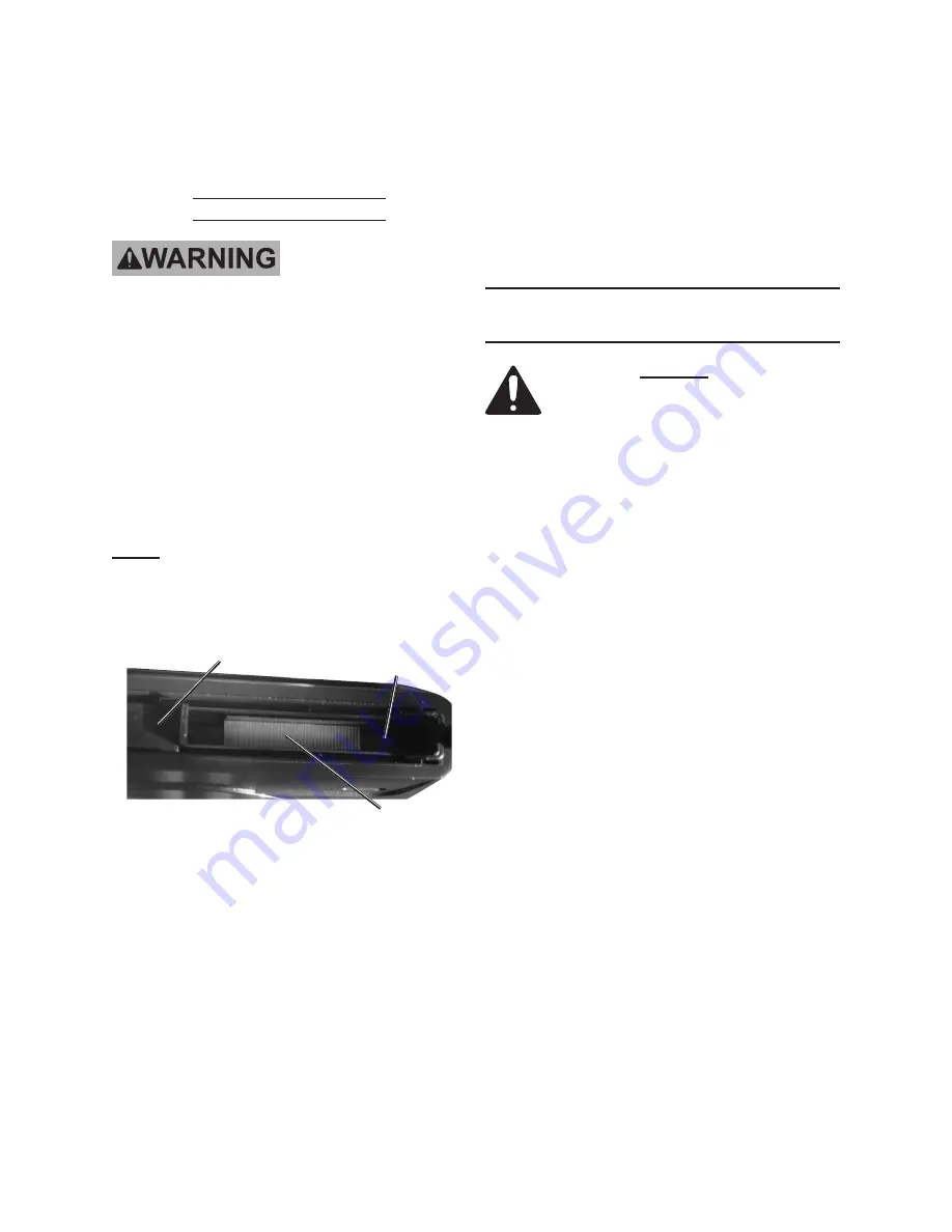
Figure A2

Magazine A (26)

Staples

Plunger (28)

3.  Place a strip of staples into Maga-

zine A (26), making sure the crown 

seats into the magazine. When us-

ing Brads, hold the Nailer/Stapler in 

a slight slant position. This will keep 

the Brad strip in the groove until the 

Plunger (28) is pressed in to lock. 

Insert the flat end into the groove at 

the left-hand side of the Magazine A.  

See 

Figure A2


WARNINg! DO NOT LOAD STA-

PLES AND BRAD NAILS AT THE 

SAmE TImE.

Slide the Plunger into the Nailer/Sta-

4. 

pler’s Housing (1,2) until the Maga-

zine Trigger re-latches. 

gENERAL OPERATINg 

INSTRuCTIONS

Read the ENTIRE ImPORTANT 

SAFETy INFORmATION section 

at the beginning of this manual 

including all text under 

subheadings therein before set 

up or use of this product.
use of any accessory or 

attachment other than those 

listed below may increase the 

risk of serious injury.
Do not activate Nailer/Stapler 

unless it is pressed against the 

workpiece.  Do not point the 

Nailer/Stapler at  yourself or 

other people.

REV 08j

Summary of Contents for 65796

Page 1: ...l Copyright 2008 by Harbor Freight Tools All rights reserved No portion of this manual or any artwork contained herein may be reproduced in any shape or form without the express written consent of Harbor Freight Tools Diagrams within this manual may not be drawn proportionally Due to continuing improvements actual product may differ slightly from the product described herein Tools required for ass...

Page 2: ...the safety alert symbol indicates a hazardous situation which if not avoided could result in minor or moderate injury NOTICE is used to address practices not related to personal injury CAUTION without the safety alert symbol is used to address practices not related to personal injury When using power tools basic safety precautions should always be followed to reduce the risk of fire electric shock...

Page 3: ...ersonal injury Do not overreach Keep proper e footing and balance at all times Proper footing and balance enables better control of the tool in unexpect ed situations f Use safety equipment A dust mask non skid safety shoes and a hard hat must be used for the applicable conditions Wear heavy duty work gloves during use Wear a full face shield if you are producing metal filings or wood chips g Alwa...

Page 4: ...nly accessories that are m identified by the manufacturer for the specific tool model Use of an accessory not intended for use with the specific tool model increases the risk of injury to persons Service Tool service must be performed a only by qualified repair personnel When servicing a tool use only b identical replacement parts Use only authorized parts Use only lubricants supplied with c tool ...

Page 5: ...ors which cannot be built into product but must be supplied by the operator Vibration Hazard This tool vibrates during use Re peated or long term exposure to vibra tion may cause temporary or permanent physical injury particularly to the hands arms and shoulders To reduce the risk of vibration related injury Anyone using vibrating tools regu 1 larly or for an extended period should first be examin...

Page 6: ...he following pages refer to the Assembly Diagram near the end of this manual Charging Battery Pack Charge Battery 22 only with the 18V 1 charger provided Charge indoors only Figure A Charger Stand 33 Battery 22 Cord for Charger 32 2 Insert Battery Pack into Charger Stand 33 Plug Charger 32 into appropriate AC 120V 60 Hz power outlet See Figure A above The red LED light on Charger Stand will acti v...

Page 7: ...n seats into the magazine When us ing Brads hold the Nailer Stapler in a slight slant position This will keep the Brad strip in the groove until the Plunger 28 is pressed in to lock Insert the flat end into the groove at the left hand side of the Magazine A See Figure A2 WARNING DO NOT LOAD STA PLES AND BRAD NAILS AT THE SAME TIME Slide the Plunger into the Nailer Sta 4 pler s Housing 1 2 until th...

Page 8: ...e 6 against the workpiece without pulling the Trigger The tool must not cycle fire If it cycles fires stop immedi ately and have it repaired by a quali fied service technician Hold the tool away or off the work 7 piece in a safe direction The Nose should return to its original posi tion Squeeze the Trigger The tool should not cycle fire If the tool cycles fires stop immediately and have it repaire...

Page 9: ... Maga 6 zine Then press the Magazine Trig ger and slide the Magazine forward all the way Attempt to fire the Nailer Stapler into 7 a piece of scrap wood to ensure it is disconnected and is incapable of fir ing any fasteners With the Nailer Stapler on its side 8 use a screwdriver not included to remove the bolts along the top of the Left and Right Housing 1 2 Re move Housing and then remove the Dri...

Page 10: ...edures To prevent serious injury from tool failure Do not use damaged equipment If abnormal noise vibration or air leaks occurs have the problem corrected before further use Cleaning Maintenance and Lubrication Note Anytime inspection maintenance and cleaning are done Disconnect the Battery from the 1 Nailer Stapler Empty the Magazine 26 complete 2 ly of fasteners Wipe down exterior of the Nailer ...

Page 11: ... repairs to the original product or replacement parts thereto or arising out of his or her installation of replacement parts thereto Troubleshooting Problem Possible Causes Likely Solutions Lack of power Slow to cycle Low power when shooting and returning Battery not properly charged 1 Improper setting 2 Charge Battery for 3 hours 1 Adjust Select Dial 8 to correct 2 setting Not shooting fasteners ...

Page 12: ...ng Pad 1 13 Drive Unit 1 14 Iron Wheel 1 15 Gear 1 16 Axis 1 17 Gear 1 PARTS LIST Part Description Q ty 18 Gear Support 1 19 Support 1 20 Axis Gear 1 21 Motor 1 22 Battery 1 23 Safety Pad 1 24 Safety 1 25 Spring 1 26 Magazine A 1 27 Pusher 1 28 Plunger 1 29 Spring 1 30 Magazine Release 1 31 Spring 1 32 Charger 1 33 Charger Stand 1 31 30 29 28 27 26 25 24 23 8 9 10 11 12 13 1 21 19 15 14 16 17 18 2...

Page 13: ...r limitation of incidental or consequential damages so the above limitation of exclusion may not ap ply to you This warranty is expressly in lieu of all other warranties express or implied including the warranties of merchantability and fitness To take advantage of this warranty the product or part must be returned to us with transportation charges prepaid Proof of purchase date and an explanation...

Reviews: