background image

SKU 66523 

For technical questions, please call 1-800-444-3353. 

Page 23

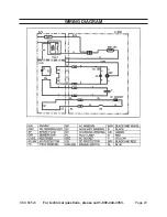
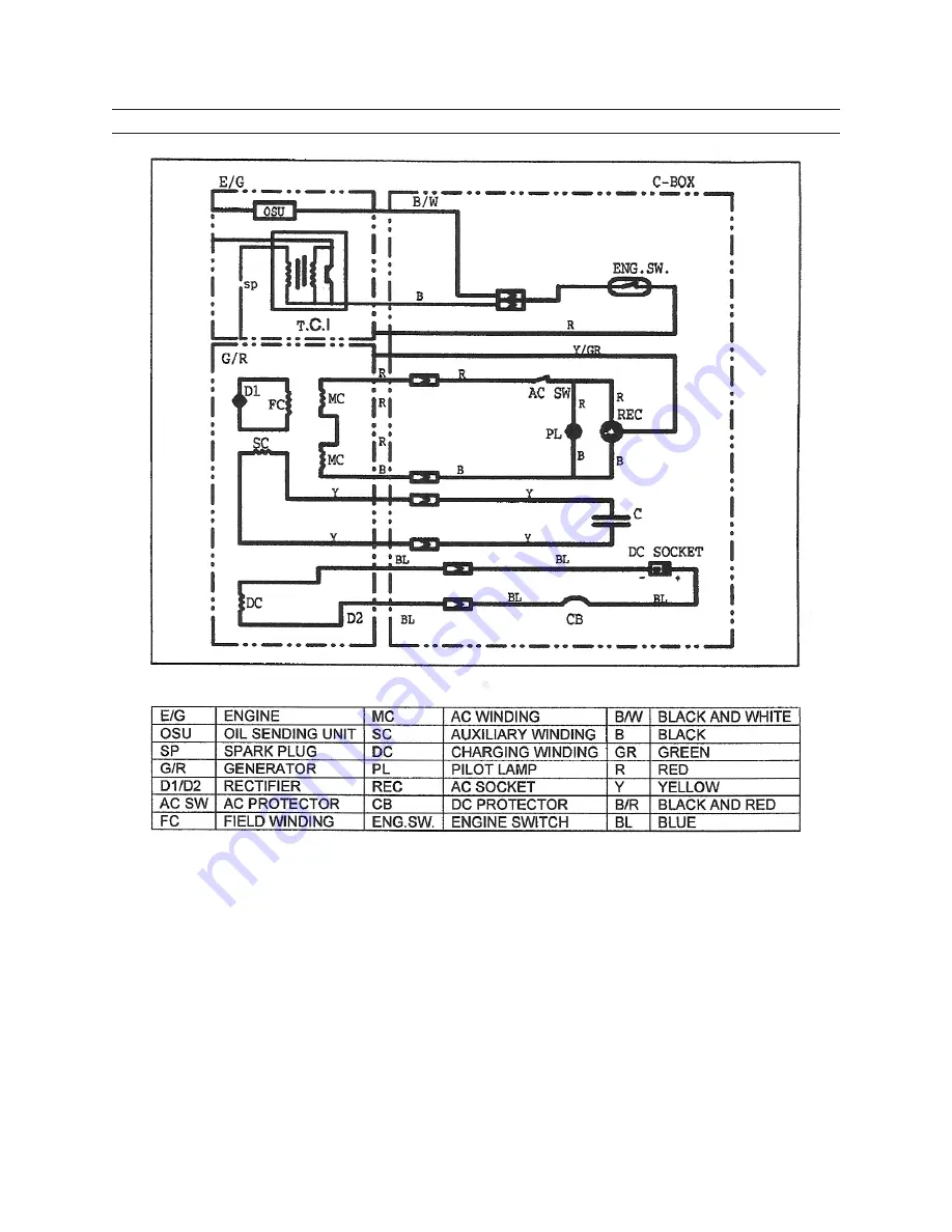
WIRING dIAGRAM

Summary of Contents for 66516

Page 1: ...at http www harborfreight com Read this material before using this product Failure to do so can result in serious injury Save this manual Copyright 2008 by Harbor Freight Tools All rights reserved No portion of this manual or any artwork contained herein may be reproduced in any shape or form without the express written consent of Harbor Freight Tools Diagrams within this manual may not be drawn p...

Page 2: ... SERVICE PRECAUTIONS 5 GENERATOR PRECAUTIONS 6 BASIC ENGINE SPECIFICATIONS 7 UNPACKING 7 OPERATING INSTRUCTIONS 7 TECHNICAL SPECIFICATIONS 12 SERVICING 12 TROUBLESHOOTING ENGINE 15 TROUBLESHOOTING GENERATOR 17 PARTS LIST 18 ASSEMBLY DIAGRAM 19 PARTS LIST ENGINE 20 ASSEMBLY DIAGRAM ENGINE 21 WIRING DIAGRAM 22 WARRANTY INFORMATION 23 PLEASE READ THE FOLLOWING 24 ...

Page 3: ...n which if not avoided could result in minor or moderate injury NOTICE is used to address practices not related to personal injury CAUTION without the safety alert symbol is used to address practices not related to personal injury WARNING Read all instructions Failure to follow all instructions listed below may result in fire serious injury and or DEATH The warnings and precautions discussed in th...

Page 4: ...ith 5 the Engine running Do not sit or stand on this machine 6 Do not tilt the machine while the En 7 gine is running Do not leave the Generator unattend 8 ed when it is running Turn off the Engine before leaving the area Wear ANSI approved safety goggles 9 hearing protection and heavy duty work gloves during use People with pacemakers should 10 consult their physician s before use Electromagnetic...

Page 5: ...fects or other reproduc tive harm California Health Safety Code 25249 5 et seq When spills of fuel or oil occur they 22 must be cleaned up immediately Dispose of fluids and cleaning materi als as per any local state or federal codes and regulations Store oil rags in a bottom ventilated covered metal container Before use check for misalignment 23 or binding of moving parts breakage of parts and any...

Page 6: ...tions GENERATOR PRECAUTIONS Set Up Do not connect the Generator directly 1 into a home s utility electrical line Do not plug this Generator into an outlet in the home Connecting a generator directly to a utility power supply can back feed along the power lines and kill or injure utility workers working on the lines All connections and conduits from 2 the Generator to the load must only be installe...

Page 7: ...e the insulation is cracked cut abrad ed or otherwise degraded Replace terminals that are worn discolored or corroded Keep terminals clean and tight Basic Specifications Fuel Type 91 octane unleaded gasoline Capacity 1 3 Gallons Engine Oil Type SAE 10W 30 Capacity 13 5 Ounces Note Additional specifications found in the Technical Engine Specifi cations chart in this manual The emission control syst...

Page 8: ...filled with oil before each use Before each use check the oil level Do not run the Engine with low or no engine oil Running the Engine with no or low engine oil WILL permanently damage the Engine Remove the Engine s Dipstick and 1 wipe it off with a clean rag See Figure A Reinsert the Dipstick completely 2 but do not screw it in and remove it to check the oil level The oil level should be between ...

Page 9: ...eaded gasoline mixture See Figure B Then replace the Fuel Tank Cap 14 6 See Figure B Start Procedure Before starting the Engine Inspect the equipment and En a gine Fill the Engine with the proper b amount and type of fuel and oil See Figures A and B NOTE Only after the Genera c tor has stabilized and is running smoothly should an appliance or tool be plugged into the AC Outlet of the Generator Tur...

Page 10: ... the Engine will help to 1 ensure proper equipment and Engine operation and will extend the En gine s lifespan The warranty is void if the Engine is not broken in properly The first 25 hours of operation is the break in period During this time frame DO NOT exceed 75 of the Generator s load limit In other words the maximum load during this break in period should be no more than 700 watts After the ...

Page 11: ... outlet Refer to appliance tool owner s manuals to determine the wattage of electrical load devices Long power cords and extension cords draw additional power Keep cord length at a minimum See Figure G FIGURE G AC Application Allow the Engine to run at no load 1 until warm approx 3 minutes after each start up to allow the Engine to stabilize Plug the power cord of the 120 volt 2 appliance tool int...

Page 12: ...egative terminal on the battery See Figure I When finished charging the battery 6 unplug the DC Outlet Cord from the DC Outlet on the Generator Then disconnect the Cord clamps from the battery See Figure I If charing a DC battery on a vehicle 7 always clamp the negative wire of the Generator to a good ground connec tion on the chassis FIGURE I 12 VDC BATTERY NOT INCLUDED DC OUTLET CORDS DC OUTLET ...

Page 13: ...ment If abnormal noise vibration or excess smoking occurs have the problem corrected before further use Maintenance Procedures Many maintenance procedures including those not detailed in this manual will need to be performed by a qualified technician for safety If you have any doubts about your ability to safely service the equipment or Engine have a qualified technician service the equipment inst...

Page 14: ...e existing spark plug adjust the Plug s gap to the specifi cation on the Technical specification chart and in the illustration below Do not pry against the electrode or the insulator the Spark Plug can be dam aged See Figure J Install the new Spark Plug or the 5 cleaned Spark Plug into the Engine Gasket style Finger tighten until the gasket contacts the cylinder head then about 1 2 2 3 turn more N...

Page 15: ...ug b Remove Spark Plug and pour one tablespoon of engine oil into Cylin der through Spark Plug hole Reinstall Spark Plug but leave the c Spark Plug Wire disconnected Pull Starter Handle to distribute oil d in Cylinder Stop after one or two revolutions when you feel the Piston start the compression stroke when you start to feel resistance Apply a thin coat of rust preventive oil 3 to all uncoated m...

Page 16: ...d set choke to start position Ignition spark Related Spark plug wire not connected 1 securely Spark plug electrode wet or dirty 2 Incorrect spark plug gap 3 Spark plug wire or spark plug 4 broken Incorrect spark timing or faulty 5 ignition system Ignition spark Related Connect spark plug wire properly 1 Clean spark plug 2 Correct spark plug gap 3 Replace spark plug wire and or 4 spark plug Have qu...

Page 17: ...ed gasoline Test replace fuel tank cap 3 Properly adjust idle speed 4 Have qualified technician diagnose 5 and service engine Engine knocks Old or low quality gasoline 1 Engine overloaded 2 Incorrect spark timing deposit 3 buildup worn engine or other mechanical problems Fill fuel tank with fresh 91 octane 1 unleaded gasoline Do not exceed equipment s load 2 rating Have qualified technician diagno...

Page 18: ... technical questions please call 1 800 444 3353 Page 18 TROUBLESHOOTING GENERATOR UNIT Problem Possible Cause Possible Solutions Follow all safety precautions whenever diagnosing or servicing the equipment or engine ...

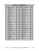
Page 19: ... x 25 2 16 Breather 1 54 Petcock Assy 1 18 Fuel Cap Ring 1 55 Capacitor Mount 1 19 Filter Basket 1 56 Capacitor 1 20 Fuel Tank 1 57 Forward Shroud 1 21 Handle Cover 1 58 Oil Inspection Assy 1 22 Spark Plug Boot 1 59 Control Panel 1 23 Back Shroud 1 60 AC Circuit Breaker 1 24 Washer 6 11 61 AC Outlet 1 25 Screw M6 x 16 11 62 Screw M4 x 16 2 26 Choke Cover 1 63 Self Tapping Screw ST4 2 x 15 2 27 Muf...

Page 20: ...SKU 66523 For technical questions please call 1 800 444 3353 Page 20 ASSEMBLY DIAGRAM GENERATOR ...

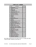
Page 21: ...Pusher 2 16 Regulating frame assembly 1 17 Muffler assembly 1 18 Cylinder head assembly 1 19 Exhaust valve Intake valve 2 20 Valve spring 2 21 Valve rocker assembly 1 22 Cylinder head cover gasket 1 23 Cylinder head cover assembly 1 24 Carburetor 1 25 Air cleaner assembly 1 26 Ignition coil assembly 1 27 Flywheel 1 28 Flywheel fan 1 29 Starting flange 1 30 Fan hood assembly 1 31 Recoil starter ass...

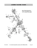
Page 22: ...stions please call 1 800 444 3353 Page 22 ASSEMBLY DIAGRAM ENGINE 1 6 11 17 27 2 7 12 18 28 3 8 13 23 33 19 29 4 9 14 24 20 30 5 10 15 25 21 31 16 26 22 32 Note When referencing parts on this diagram add an A suffix to the number ...

Page 23: ...SKU 66523 For technical questions please call 1 800 444 3353 Page 23 WIRING DIAGRAM ...

Page 24: ...ment The California Air Resources Board herein CARB the United States Environmental Protection Agency herein EPA and Harbor Freight Tools herein HFT are pleased to explain the emission control system warranty on your 1995 and later Small Off Road Engine herein engine In California the engine must be designed built and equipped to meet the State s stringent anti smog standards Elsewhere within the ...

Page 25: ...t scheduled for replace ment as required maintenance or are scheduled only for regular inspection to the effect of repair or replace as necessary are warranted for the warranty period Any warranted part which is scheduled for replacement as required maintenance is warranted for the period of time up to the first scheduled replacement point for that part Any replacement part provided it is equivale...

Reviews: