background image

Page 16

For technical questions, please call 1-800-444-3353.

SKU 66615 


Part

description

Qty.

1

Screw

5

2

Right Handle

1

4

Circuit Board

1

5

Power Cord & Plug

1

6

Cord Stress Relief

1

7

Cord Retaining Bracket

1

8

Screw

2

9

Left Handle

1

10

Display

1

11

Power Switch

1

12

– Speed Button

1

13

+ Speed Button

1

14

Control Cover

1

15

Screw

4

16

Bracket

2

17

Brush Holder

2

18

Brush Sheath

2

19

Carbon Brush

2

22

Motor Housing

1

23

Stator

1

24

Bearing Holder

1

25

Rear Bearing

1

26

Screw

2

27

Bushing

1

28

Rotor

1

29

Screw

3

Part

description

Qty.

30

Bracket

1

31

Front Bearing

1

32

Gear Box

1

33

Screw

4

34

Spindle Lock

1

35

Spring

1

36

Auxiliary Handle

1

37

Oil Seal

1

38

Retaining Ring

1

39

Washer

1

40

Retaining Ring

1

41

Large Gear

1

42

Screw

3

43

Washer

3

44

Fixed Board

1

45

Bearing

1

46

Connecting Board

1

47

Washer

4

48

Screw

4

49

Key

1

50

Spindle

1

51

Mounting Disc

1

52

Polishing Bonnet

1

53

Foam Bonnet

1

54

Sanding Disc

1

PLEaSE REad THE FOLLOWINg CaREFuLLY

THE MANUFACTURER AND/OR DISTRIBUTOR HAS PROVIDED THE PARTS LIST AND ASSEMBLy 

DIAGRAM IN THIS MANUAL AS A REFERENCE TOOL ONLy.  NEITHER THE MANUFACTURER OR 

DISTRIBUTOR MAKES ANY REPRESENTATION OR WARRANTY OF ANY KIND TO THE BUYER THAT HE 

OR SHE IS qUALIFIED TO MAkE ANy REPAIRS TO THE PRODUCT, OR THAT HE OR SHE IS qUALIFIED 

TO REPLACE ANy PARTS OF THE PRODUCT.  IN FACT, THE MANUFACTURER AND/OR DISTRIBUTOR 

ExPRESSLy STATES THAT ALL REPAIRS AND PARTS REPLACEMENTS SHOULD BE UNDERTAkEN By 

CERTIFIED AND LICENSED TECHNICIANS, AND NOT By THE BUyER.  THE BUyER ASSUMES ALL RISk 

AND LIABILITy ARISING OUT OF HIS OR HER REPAIRS TO THE ORIGINAL PRODUCT OR REPLACEMENT 

PARTS THERETO, OR ARISING OUT OF HIS OR HER INSTALLATION OF REPLACEMENT PARTS THERETO.

PaRTS LIST

REV 10b

Summary of Contents for 66615

Page 1: ...eserved No portion of this manual or any artwork contained herein may be reproduced in any shape or form without the express written consent of Harbor Freight Tools Diagrams within this manual may not...

Page 2: ...y NOTICE is used to address practices not related to personal injury CAUTION without the safety alert symbol is used to address practices not related to personal injury General Power Tool Safety Warni...

Page 3: ...g to power source and or battery pack picking up or carrying the tool Carrying power tools with your finger on the switch or energizing power tools that have the switch on invites accidents Remove any...

Page 4: ...ety Warnings Common for Sanding or Polishing Operations This power tool is intended to 1 function as a sander or polisher Read all safety warnings instructions illustrations and specifications provide...

Page 5: ...en performing an operation where the accessory may contact hidden wiring or its own cord An accessory contacting a live wire may make exposed metal parts of the power tool live and shock the operator...

Page 6: ...afety equipment such as those dust masks that are specially designed to filter out microscopic particles California Health Safety Code 25249 5 et seq WARNING Handling the cord on this 25 product will...

Page 7: ...cause snagging tearing of the disc or kickback Safety Warnings Specific for Polishing Operations Do not allow any loose portion of the 1 polishing bonnet or its attachment strings to spin freely Tuck...

Page 8: ...a proper outlet installed by a qualified electrician Double Insulated Tools Tools with Two Prong Plugs Outlets for 2 Prong Plug Tools marked Double Insulated do not 1 require grounding They have a spe...

Page 9: ...and in good electrical condition Always replace a damaged extension cord or have it repaired by a qualified electrician before using it Protect the extension cords from sharp 8 objects excessive heat...

Page 10: ...nning of this manual including all text under subheadings therein before set up or use of this product To prevent serious injury from accidental operation Turn the Power Switch 11 off and unplug the P...

Page 11: ...See Figures A and B Make sure the accessory is placed 3 evenly on the Mounting Disc and is secure before turning on the tool Work Piece and Work Area Set Up Designate a work area that is clean and 1...

Page 12: ...lt in the Foam Bonnet 53 being thrown from the Mounting Disc 51 Grip the Polisher firmly with both hands 5 Then turn the Power Switch 11 to its ON position See Figure C DISPLAY 10 POWER SWITCH 11 SPEE...

Page 13: ...ace of the object After the polishing liquid or wax has 8 been removed from the object s surface slide the Power Switch 11 to its OFF position Then unplug the Power Cord 5 See Figure C Remove the Poli...

Page 14: ...machine washed in cold water with detergent Then machine dry the Bonnets at medium heat Carbon Brush Maintenance 3 IMPORTANT Cleaning or replacing the Carbon Brushes 19 should only be done by a quali...

Page 15: ...ied technician replace brushes Excessive noise or rattling Internal damage or wear Carbon brushes or bearings for example Have technician service tool Overheating Forcing tool to work too fast 1 Block...

Page 16: ...oard 1 45 Bearing 1 46 Connecting Board 1 47 Washer 4 48 Screw 4 49 Key 1 50 Spindle 1 51 Mounting Disc 1 52 Polishing Bonnet 1 53 Foam Bonnet 1 54 Sanding Disc 1 PLEASE READ THE FOLLOWING CAREFULLY T...

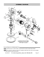
Page 17: ...18 17 16 15 1 2 14 13 12 4 11 10 9 22 23 24 25 26 8 7 6 5 Foam Bonnet 53 not shown Sanding Disc 54 not shown See Figure A page 9 Record Product s Serial Number Here Note If product has no serial numbe...

Page 18: ...cidental or consequential damages so the above limitation of exclusion may not apply to you This warranty is expressly in lieu of all other warranties express or implied including the warranties of me...

Reviews: