


SKU 66745
For technical questions, please call 1-800-444-3353.
Page 11
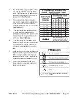
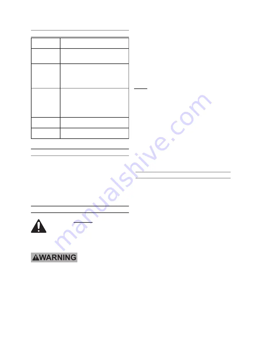
speciFicatiOns
Electrical
Requirements
120 V~ / 60 Hz / 15 A
Motor: .5 HP / Single Phase
Adjustable
Pressure
Range
0~3000 PSI (0-193 Bar)
Hose
1/4” Diameter / 25 Feet Long
Maximum Working Pressure:
3000 PSI
Maximum Working Temperature:
149° Fahrenheit (65 Celsius)
Spray Gun
1/4” External Outlet
Operating Temperature Range:
40° ~ 115° Fahrenheit /
4.4° ~ 46° Celsius
Nozzle Size:
.017” Diameter (No. 417)
Average
Delivery
0.24 GPM
Overload
Protection
Located at bottom of Motor enclosure.
unpacKing
When unpacking, check to make sure that
the item is intact and undamaged. If any
parts are missing or broken, please call
Harbor Freight Tools at the number shown
on the cover of this manual as soon as
possible.
assemBly instructiOns
read the entire impOrtant
saFety inFOrmatiOn
section at the beginning of this
manual including all text under
subheadings therein before set
up or use of this
product.
tO preVent seriOus injury
FrOm accidental OperatiOn:
turn the power switch (33a)
of the high pressure airless
sprayer to its “OFF” position
and unplug the sprayer from its
electrical outlet before assembly
procedures.
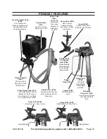
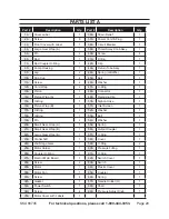
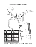
note:
For additional information regarding
the parts listed in the following pages,
refer to the Assembly Diagram near
the end of this manual.
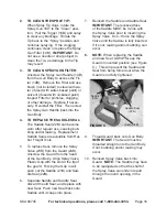
Remove the protective Plastic Cap
1.
from the Paint Output Coupler (56A).
Then attach the High Pressure Paint
Hose (20B).
Remove the protective Plastic Cap
2.
from the Spray Gun. Then attach the
other end of the High Pressure Paint
Hose to the Gun.
Workpiece and Work area set up
Designate a work area that is clean
1.
and well-lit. The work area must not
allow access by children or pets to
prevent distraction and injury.
Route the Power Cord (37A) along
2.
a safe path to reach the work area
without creating a tripping hazard
or exposing the Power Cord to pos-
sible damage. The Power Cord must
reach the work area with enough
extra length to allow free movement
while working.


