background image

SKU 66753 

for technical questions, please call 1-800-444-3353. 

Page 17

If the white insulator is cracked or 

c. 

chipped, the spark plug needs to be 

replaced.

When installing a new spark plug, ad-

4. 

just the plug’s gap to the specification 

on the Technical specification chart.  

Do not pry against the electrode or 

the insulator, the spark plug can be 

damaged.
Install the new spark plug or the 

5. 

cleaned spark plug into the engine.  

Gasket-style:  Finger-tighten until the 

gasket contacts the cylinder head, 

then about 1/2-2/3 turn more. 

Non-gasket-style: Finger-tighten until 

the plug contacts the head, then 

about 1/16 turn more.
Apply dielectric spark plug boot 

6. 

protector (not included) to the end of 

the spark plug and reattach the wire 

securely.

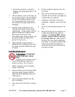
fuel filter replacement

warninG!


tO prevent 

seriOus injurY frOM 

fire:


Replace the Fuel Filter (16F) in 

a well-ventilated area away from 

ignition sources.  Do not smoke.
Wait for engine to cool completely 

1. 

before proceeding.
Wear protective gear including, ANSI-

2. 

approved safety goggles, NIOSH-

approved dust mask/respirator, and 

nitrile gloves.
Close fuel valve leading from gas 

3. 

tank completely.
Take note of the Fuel Filter’s orienta-

4. 

tion.

Place a suitable container under the 

5. 

Fuel Filter.
Disconnect the fuel lines leading to 

6. 

and from the Fuel Filter and allow fuel 

to drain onto the container.
Install new Fuel Filter in the same 

7. 

orientation.  Properly secure both fuel 

lines.
Clean up and properly dispose of all 

8. 

fuel.
Wait for at least one hour before use 

9. 

to allow all residual fuel vapors to 

dissipate. 

 to prevent fire, do not 

start the engine while the smell of 

fuel hangs in the air.

  Remember to 

open the fuel valve before restarting 

the engine.  It may take a little longer 

than usual to start the engine be-

cause the fuel needs to refill the fuel 

line and new filter.

Summary of Contents for 66753

Page 1: ... http www harborfreight com Read this material before using this product Failure to do so can result in serious injury Save this manual Copyright 2009 by Harbor Freight Tools All rights reserved No portion of this manual or any artwork contained herein may be reproduced in any shape or form without the express written consent of Harbor Freight Tools Diagrams within this manual may not be drawn pro...

Page 2: ...nd Lubrication Schedule 18 Weekly Maintenance 18 Monthly Maintenance 18 Storage 18 Troubleshooting 19 Parts Lists and DIAGRAMS 21 Drive System Parts List Diagram 21 Blade Guard Assembly Parts List Diagram 22 Flange Assembly Parts List Diagram 23 Clutch Assembly Parts List Diagram 24 Handle Assembly Parts List Diagram 24 Control System Parts List Diagram 25 Air Filter Assembly Parts List Diagram 26...

Page 3: ...ich if not avoided could result in minor or moderate injury NOTICE is used to address practices not related to personal injury CAUTION without the safety alert symbol is used to address practices not related to personal injury WARNING Read all instructions Failure to follow all instructions listed below may result in fire serious injury and or DEATH The warnings and precautions discussed in this m...

Page 4: ...emaker interference or pacemaker failure Caution is neces sary when near the engine s magneto or recoil starter Use only accessories that are recom 6 mended by Harbor Freight Tools for your model Accessories that may be suitable for one piece of equipment may become hazardous when used on another piece of equipment Do not operate in explosive atmo 7 spheres such as in the presence of flammable liq...

Page 5: ... binding of moving parts breakage of parts and any other condition that may affect the equipment s operation If damaged have the equipment serviced before using Many ac cidents are caused by poorly main tained equipment Use the correct equipment for the 21 application Do not modify the equip ment and do not use the equipment for a purpose for which it is not in tended Cut Off Saw Safety Precaution...

Page 6: ...he engine reaction drives the Cut Off Saw rapidly back toward the operator If the Saw Blade becomes twisted or misaligned in the cut the teeth at the back edge of the Saw Blade can raise the Cut Off Saw walk up toward the operator Kick back is a result of tool misuse and or incorrect operating procedures or conditions and can be avoided by taking proper precautions as given below Maintain control ...

Page 7: ...e should not use this tool If you feel any symptoms related to vibration such as tingling numbness and white or blue fingers seek medical advice as soon as pos sible Do not smoke during use Nico 2 tine reduces the blood supply to the hands and fingers increasing the risk of vibration related injury Wear suitable gloves to reduce the 3 vibration effects on the user Use tools with the lowest vibrati...

Page 8: ...the equip ment is maintained Do not attempt any service or maintenance proce dures not explained in this manual or any procedures that you are un certain about your ability to perform safely or correctly Store equipment out of the reach of 7 children Follow scheduled engine and equip 8 ment maintenance Refueling Precautions 9 Do not smoke or allow sparks a flames or other sources of ignition aroun...

Page 9: ...y the U S Environmental Protection Agency and by the California Air Resourc es Board also known as CARB For war ranty information refer to the last pages of this manual At high altitudes the engine s carbu retor governor if so equipped and any other parts that control the fuel air ratio will need to be adjusted by a qualified me chanic to allow efficient high altitude use and to prevent damage to ...

Page 10: ...roper spark arrestor installed Operation of this equipment may create sparks that can start fires around dry vegetation A spark arrestor may be required The operator should contact local fire agencies for laws or regulations relating to fire prevention requirements Note For additional information regarding the parts listed in the following pages refer to the Parts Lists and Assembly Diagrams near ...

Page 11: ...ar ring Do not use a damaged blade Installing the Blade Blade Guard 7B Hex Bolt 20C Outside Flange 5B Arbor 13C not shown Rotation Direction Arrow Figure 4 1 Loosen and remove the Hex Bolt 20C Then remove the Outside Flange 5B The Inner Flange must be oriented 2 so that it matches perfectly with the arbor hole of the blade one side is 1 and the other side is 20 mm Mount the new Saw Blade not in 3 ...

Page 12: ...only enough fuel for a few days work The maximum stor age time of mixed fuel is 3 months FUEL MIX QUANTITIES Ratio 2 Stroke Engine Oil Unleaded Gasoline 90 Octane 40 1 4 Fl Oz 1 2 Gal 40 1 8 Fl Oz 2 4 Gal Once the proper fuel mix is obtained 3 wipe gas cap 17F and its surround ing area then remove the Gas Cap Fill the Fuel Tank approximately 3 4 full with the fuel mix the Fuel Tank capacity is 0 1...

Page 13: ...This can damage the saw Hold the Starter Handle and guide the Starter Cord as it recoils back into the machine Once the engine starts squeeze the 7 Trigger The engine should idle down but not cut off If the Choke was pulled out slowly 8 push in the choke IMPORTANT Allow the engine to run at no load until warm 1 5 minutes after each start up to allow the engine to stabilize If the engine does not s...

Page 14: ...rds and forwards using a small part of the cutting edge of the blade to slowly cut material Do not cut only in one direction See Figure 6 Keep the blade at a right angle to the 5 cutting surface Never cut above shoulder height 6 Figure 7 7 To avoid kickback never cut with the upper section of the blade See Figure 7 Abrasive Blades are not intended for 8 use with water When cutting concrete always ...

Page 15: ...er use Maintenance Procedures Many maintenance procedures including those not detailed in this manual will need to be performed by a qualified technician for safety If you have any doubts about your ability to safely service the equipment or engine have a qualified technician service the equipment instead Note Warranty is void if proper mainte nance and servicing procedures are not followed Coolin...

Page 16: ... filter from the side oppo site the filter s normal air flow the clean side of the filter If this does not get the filter reason ably clean replace it For the Foam Filter 4G b Wash the element in warm water and mild detergent several times Rinse thoroughly Squeeze out ex cess water and allow it to dry com pletely Soak the filter in lightweight oil briefly then squeeze out the excess oil Install th...

Page 17: ...Replace the Fuel Filter 16F in a well ventilated area away from ignition sources Do not smoke Wait for engine to cool completely 1 before proceeding Wear protective gear including ANSI 2 approved safety goggles NIOSH approved dust mask respirator and nitrile gloves Close fuel valve leading from gas 3 tank completely Take note of the Fuel Filter s orienta 4 tion Place a suitable container under the...

Page 18: ... der 1K Check the muffler d Check the carburetor e Blow dust off with compressed air f Monthly Maintenance Check the clutch drum drive pulley a clutch springs for wear Clean the outside of the carburetor b Check the fuel filter and fuel hose c Change if needed Clean the inside of the fuel tank d Check all cables and connections e Storage Wait for engine to cool then clean 1 engine with clean cloth...

Page 19: ...plug wire disconnected or not 1 connected securely Spark plug electrode wet or dirty 2 Incorrect spark plug gap 3 Spark plug wire or spark plug 4 broken Incorrect spark timing or faulty 5 ignition system Ignition spark Related Connect spark plug wire properly 1 Clean spark plug 2 Correct spark plug gap 3 Replace spark plug wire and or 4 spark plug Have qualified technician diagnose 5 repair igniti...

Page 20: ...r mechanical problems Empty fuel tank and re fill with fresh 1 90 octane unleaded gasoline 40 1 mixture with 2 stroke engine oil Do not exceed equipment s load 2 rating Have qualified technician diagnose 3 and service engine Engine backfires Impure or low quality gasoline 1 Choke not open after engine warm 2 Engine not properly adjusted for 3 high altitude operation Intake valve stuck choke stuck ...

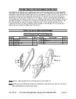
Page 21: ...at all repairs and parts replacements should be undertaken by certified and licensed technicians and not by the buyer The buyer assumes all risk and liability arising out of his or her repairs to the original product or replacement parts thereto or arising out of his or her installation of replacement parts thereto Parts Lists and DIAGRAMS Drive System Parts List Diagram Part Description Qty 1A Ba...

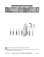
Page 22: ...Washer 1 3B Washer 2 4B Guard Flange 1 5B Outside Flange 1 Part Description Qty 6B Inside Flange 1 7B Blade Guard 1 8B Adjustment Handle 1 9B Spacer 2 10B Bolt 2 Note When ordering parts for this component use the suffix B Note Some parts are listed and shown for illustration purposes only and are not avail able individually as replacement parts ...

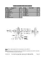
Page 23: ... 6C Belt Tensioner 1 7C Spacer 1 8C Screw 1 9C Bracket 1 10C Bolt 1 11C Rubber Washer 1 Part Description Qty 12C Bolt 1 13C Arbor 1 14C Spring 4 15C Spacer 4 16C Bolt 4 17C Pulley 1 18C Washer 1 19C Nut 1 20C Hex Bolt 1 Note When ordering parts for this component use the suffix C Note Some parts are listed and shown for illustration purposes only and are not avail able individually as replacement ...

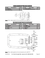
Page 24: ...ty 4D Clutch Washer 1 5D Centrifugal Clutch Assembly 1 Note When ordering parts for this component use the suffix D Handle Assembly Parts List Diagram Part Description Qty 1E Bracket 1 2E Washer 8 3E Bolt 6 4E Roller Shaft 1 5E Bolt 2 Part Description Qty 6E Roller 2 7E Roller Screw 2 8E Front Handle 1 9E Washer 2 10E Bolt 2 Note When ordering parts for this component use the suffix E ...

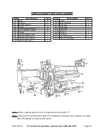
Page 25: ...ring Piece 1 9F Trigger Safety Lever 1 10F Throttle Catch Spring 1 11F Left Handle Cover 1 Part Description Qty 12F Screw 2 13F Tank Complete 1 14F Fuel Line 1 15F Tank Vent 1 16F Fuel Filter 1 17F Gas Cap 1 18F O Ring 1 19F Pot Hook 1 20F Fuel Line Clamp 1 23F Gas Cap Complete 1 Note When ordering parts for this component use the suffix F Note Some parts are listed and shown for illustration purp...

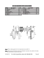
Page 26: ...m Filter 1 5G Air Filter Cover 1 6G Washer 6 7G Bolt 3 8G Seal 1 Part Description Qty 9G Air Filter Base 1 10G Bolt 3 11G Seal 1 12G Paper Filter 1 13G Filter Screen 1 14G ON OFF Switch 1 17G Grommet 1 Note When ordering parts for this component use the suffix G Note Some parts are listed and shown for illustration purposes only and are not avail able individually as replacement parts ...

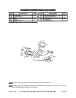
Page 27: ...Bolt 2 4H Gasket 1 5H Breather Hose 1 6H Choke 1 Part Description Qty 7H Carburetor Assembly 1 8H Throttle Linkage Holder 1 9H Throttle Bushing 1 10H Throttle Rod 1 11H Throttle Spring 1 Note When ordering parts for this component use the suffix H Note Some parts are listed and shown for illustration purposes only and are not avail able individually as replacement parts ...

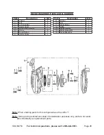
Page 28: ...l Spring Mount 1 6I Screw 4 7I Recoil Spring 1 8I Starter Pulley 1 Part Description Qty 9I Washer 1 10I Bolt 1 11I Starter Rope 1 12I Baffle 1 13I Starter Handle 1 15I Starter Assembly 1 16I Recoil Assembly 1 Note When ordering parts for this component use the suffix I Note Some parts are listed and shown for illustration purposes only and are not avail able individually as replacement parts ...

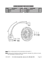
Page 29: ... Qty 1J Flywheel Assembly 1 2J Washer 1 3J Washer 1 4J Nut 1 Part Description Qty 5J Ignition Assembly 1 6J Washer 2 7J Washer 2 8J Bolt 2 Note When ordering parts for this component use the suffix J Note Some parts are listed and shown for illustration purposes only and are not avail able individually as replacement parts ...

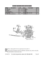
Page 30: ... Plug 1 5K Intake Manifold 1 6K Clamp 1 7K Cylinder Breather Hose 1 Part Description Qty 8K Holder 1 9K Washer 3 10K Bolt 2 11K Bolt 1 12K Gasket 1 13K Decompression Valve 1 14K Spring 1 Note When ordering parts for this component use the suffix K Note Some parts are listed and shown for illustration purposes only and are not avail able individually as replacement parts ...

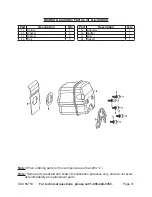
Page 31: ...cription Qty 1L Holder 1 2L Washer 3 3L Washer 2 4L Bolt 3 Part Description Qty 5L Deflector 1 6L Muffler 1 7L Bolt 2 8L Gasket 1 Note When ordering parts for this component use the suffix L Note Some parts are listed and shown for illustration purposes only and are not avail able individually as replacement parts ...

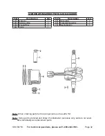
Page 32: ...M Wrist Pin 1 2M Retaining Ring 2 3M Woodruff Key 1 4M Piston 1 Part Description Qty 5M Piston Ring 2 6M Crankshaft Assembly 1 7M Needle Bearing 1 Note When ordering parts for this component use the suffix M Note Some parts are listed and shown for illustration purposes only and are not avail able individually as replacement parts ...

Page 33: ...r 1 4N Seal 1 5N Crankcase Ball Bearing 2 6N Washer 7 7N Bolt 2 Part Description Qty 8N Bolt 4 9N Bolt 1 10N Guide Pin 2 11N Crankcase Right 1 12N Grommet 1 13N Stud Bolt 2 14N Seal 1 Note When ordering parts for this component use the suffix N Note Some parts are listed and shown for illustration purposes only and are not avail able individually as replacement parts ...

Page 34: ...ation purposes only and are not avail able individually as replacement parts Wet Cutting Kit Parts List Diagram Part Description Qty 1O Bolt 1 2O Washer 1 3O Water Valve Tubing 1 Part Description Qty 4O Tie Wrap 1 5O Quick Connect Hose Fitting 1 5 Note When ordering parts for this component use the suffix O Note Some parts are listed and shown for illustration purposes only and are not avail able ...

Page 35: ...nvironmental ProtectionAgency herein EPA and Harbor Freight Tools herein HFT are pleased to explain the emission con trol system warranty on your 1995 and later Small Off Road Engine herein engine In California the engine must be designed built and equipped to meet the State s stringent anti smog standards Elsewhere within the United States new off road spark ignition engines certified for model y...

Page 36: ... and operating instructions set forth in the Owner s Manual includ ing but not limited to Use of parts which are not authorized by HFT a Improper installation adjustment or repair of the engine b or of any warranted part unless performed by an autho rized warranty center Failure to follow recommendations on fuel use contained c in the Owner s Manual Improper or inadequate maintenance of any warran...

Reviews: