
Page 3
For technical questions, please call 1-800-444-3353.
SKU 67648
SAVe thiS MAnuAl
Keep this manual for the safety warnings
and precautions, assembly, operating,
inspection, maintenance and cleaning
procedures. Write the product’s serial number
in the back of the manual near the assembly
diagram (or month and year of purchase if
product has no number). Keep this manual
and the receipt in a safe and dry place for
future reference.
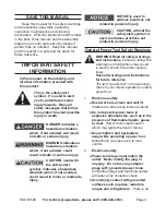
iMpOrtAnt SAFetY
inFOrMAtiOn
in this manual, on the labeling, and
all other information provided with
this product:
this is the safety alert
symbol. it is used to alert
you to potential personal
injury hazards. Obey all
safety messages that follow
this symbol to avoid possible
injury or death.
dAnger indicates a
hazardous situation
which, if not avoided, will result
in death or serious injury.
wArning indicates a
hazardous situation
which, if not avoided, could
result in death or serious injury.
cAutiOn, used with
the safety alert
symbol, indicates a hazardous
situation which, if not avoided,
could result in minor or moderate
injury.
nOtice is used to
address practices not
related to personal injury.
cAutiOn, without the
safety alert symbol, is
used to address practices not
related to personal injury.
general power tool Safety warnings
wArning read all safety warnings
and instructions.
Failure to follow the
warnings and instructions may result
in electric shock, fire and/or serious
injury.
Save all warnings and instructions
for future reference.
The term ″power tool″ in the warnings
refers to your mains-operated (corded)
power tool.
work area safety
1.
Keep work area clean and well lit.
a.
Cluttered or dark areas invite accidents.
do not operate power tools in
b.
explosive atmospheres, such as in the
presence of flammable liquids, gases
or dust.
Power tools create sparks
which may ignite the dust or fumes.
Keep children and bystanders
c.
away while operating a power tool.
Distractions can cause you to lose
control.
electrical safety
2.
power tool plugs must match the
a.
outlet. never modify the plug in
any way. do not use any adapter
plugs with grounded power tools.
Unmodified plugs and matching outlets
will reduce risk of electric shock.
Avoid body contact with grounded
b.
surfaces such as pipes, radiators,
ranges and refrigerators.
There is an