background image

Page 14

For technical questions, please call 1-800-444-3353.

Item 68993 


Sa
FE

ty

Op
ER
ati

O

n

m

aint

Enanc

E

SE

tup

part

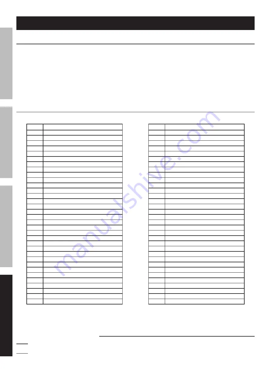
Description

1

Depth Adjustment Knob

2

Nut

3

Spring

4

Guide

5

Slide

6

Buffer

7

Rail Track

8

Left Housing

9

Spring

10

Safety Nosepiece

11

Screw

12

Driver Cover

13

Firing Nose

14

Driver

15

Nose

16

Magazine B

17

Nut

18

Support

19

Screw

20

Support

21

Nut

22

Magazine A

23

Feeder Shoe

24

Plastic Pole

25

Spring

26

Magazine C

27

Pin

28

Magazine Lock

29

Spring

30

Clip

31

Plate

32

Pin

33

Cam

part

Description

34

Main Shaft

35

Ball Bearing

36

C-Ring

37

Gearbox

38

Pinion Set

39

Gear

40

Planetary Gear

41

Gear

42

Planetary Gear

43

Gear

44

Planetary Gear

45

Gear

46

Washer

47

Motor Holder

48

Spring

49

Plastic Pole

50

Trigger

51

Spring

52

Lever

53

Trigger

54

Right Housing

55

Screw

56

Tag

57

Motor with Pinion

58

Switch A

59

Switch B

60

Battery Pack

61

Quick Charger (not shown)

62

AC/DC Adapter (not shown)

63

500 Staples (not shown)

64

500 Nails (not shown)

65

Hex Key (not shown)

66

Case (not shown)

parts list and Diagram

plEaSE REaD thE FOllOWinG caREFully

THE MANUFACTURER AND/OR DISTRIBUTOR HAS PROVIDED THE PARTS LIST AND ASSEMBLy DIAGRAM 

IN THIS MANUAL AS A REFERENCE TOOL ONLy.  NEITHER THE MANUFACTURER OR DISTRIBUTOR 

MAKES ANy REPRESENTATION OR WARRANTy OF ANy KIND TO THE BUyER THAT HE OR SHE IS 

QUALIFIED TO MAKE ANy REPAIRS TO THE PRODUCT, OR THAT HE OR SHE IS QUALIFIED TO REPLACE 

ANy PARTS OF THE PRODUCT.  IN FACT, THE MANUFACTURER AND/OR DISTRIBUTOR ExPRESSLy 

STATES THAT ALL REPAIRS AND PARTS REPLACEMENTS SHOULD BE UNDERTAKEN By CERTIFIED AND 

LICENSED TECHNICIANS, AND NOT By THE BUyER.  THE BUyER ASSUMES ALL RISK AND LIABILITy 

ARISING OUT OF HIS OR HER REPAIRS TO THE ORIGINAL PRODUCT OR REPLACEMENT PARTS 

THERETO, OR ARISING OUT OF HIS OR HER INSTALLATION OF REPLACEMENT PARTS THERETO.

parts list

Record product’s Serial number here: 
note: if product has no serial number, record month and year of purchase instead.

note:

 Some parts are listed and shown for illustration purposes only, 

and are not available individually as replacement parts.

Summary of Contents for 68993

Page 1: ...continuing improvements actual product may differ slightly from the product described herein Tools required for assembly and service may not be included When unpacking make sure that the product is intact and undamaged If any parts are missing or broken please call 1 800 444 3353 as soon as possible Save This Manual Keep this manual for the safety warnings and precautions assembly operating inspec...

Page 2: ...moderate injury Addresses practices not related to personal injury Important Safety Information General Tool Safety Warnings Read all safety warnings and instructions Failure to follow the warnings and instructions may result in electric shock fire and or serious injury Save all warnings and instructions for future reference The term tool in the warnings refers to your battery operated cordless to...

Page 3: ...0 Only use safety equipment that has been approved by an appropriate standards agency Unapproved safety equipment may not provide adequate protection Eye protection must be ANSI approved and breathing protection must be NIOSH approved for the specific hazards in the work area Tool use and care 1 Use clamps or another practical way to secure and support the workpiece to a stable platform Holding th...

Page 4: ...fasteners 5 Do not point the tool toward yourself or anyone whether it contains fasteners or not 6 Do not actuate the tool unless the tool is placed firmly against the workpiece 7 Respect the tool as a working implement 8 No horseplay This tool is not a toy and can be deadly if misused 9 Do not load the tool with fasteners when any one of the operating controls such as the Trigger or Safety Nosepi...

Page 5: ...e In addition people with pacemakers should Avoid operating alone Do not use with power switch locked on Properly maintain and inspect to avoid electrical shock 29 WARNING Handling the cord on this product s Charger will expose you to lead a chemical known to the State of California to cause cancer and birth defects or other reproductive harm Wash hands after handling California Health Safety Code...

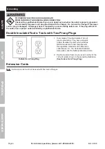
Page 6: ...e use If the plug will not fit the outlet have a proper outlet installed by a qualified electrician Double Insulated Tools Tools with Two Prong Plugs Outlets for 2 Prong Plug 1 Tools marked Double Insulated do not require grounding They have a special double insulation system which satisfies OSHA requirements and complies with the applicable standards of Underwriters Laboratories Inc the Canadian ...

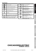
Page 7: ...jury Wear ANSI approved safety goggles with side shields Read the manual before set up and or use WARNING marking concerning Risk of Hearing Loss Wear hearing protection WARNING marking concerning Risk of Fire Do not cover Charger ventilation ducts Charge on fireproof surface only WARNING marking concerning Risk of Electric Shock Properly connect Charger s power cord to appropriate outlet WARNING ...

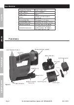
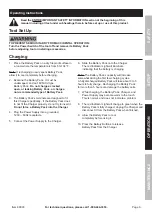
Page 8: ...s Nail Size 18 gauge x 1 1 4 Long Accepts Staple Size 18 gauge 1 4 crown 1 Long Magazine Capacity 100 brad nails or 100 staples Included Accessories 18V Battery Quick Charger AC DC Adapter 500 Staples 500 Nails Hex Key Case Functions Figure 1 Depth Adjustment Knob 1 Battery Pack 60 Lock Button AC DC Adapter 62 Shown with Battery installed Indicator Light Trigger 53 Quick Charger 61 Magazine Assemb...

Page 9: ...terminals are designed to fit this Charger specifically If the Battery Pack does to not fit the Charger properly do not try to insert it Do not force a Battery Pack into the Charger 4 Plug the Power Supply into a grounded 120V 60Hz receptacle 5 Connect the Power Supply to the Charger 6 Slide the Battery Pack onto the Charger The red Indicator Light will illuminate indicating that the battery is ch...

Page 10: ...nsert staples or brads into the magazine so that the pointed ends are facing outward 3 Slide the Magazine back in place until the Magazine Lock is secured in place Depth Adjustment 1 Figure 4 Depth Adjustment Knob More pressure Less pressure The Depth Adjustment Knob controls the amount of force used to shoot a staple or brad 2 Install the Battery Pack and nails or staples 3 Turn the Knob clockwis...

Page 11: ... tool away or off of the workpiece The Safety Nosepiece should return to its original position Squeeze the Trigger The tool must not cycle fire If it cycles fires stop immediately and take the tool to a qualified service technician 7 Press the Safety Nosepiece against the workpiece and squeeze the Trigger The tool must cycle fire only once Release the Trigger and squeeze it again The tool must cyc...

Page 12: ...ttempt to fire the Tool into a piece of scrap wood to ensure that it is disconnected and is incapable of firing any fasteners Empty the magazine and leave it open during service The Magazine is spring loaded and may cause parts or a fastener to fly out of the Tool 1 If a fastener is jammed in the discharge area remove it with pliers 2 If the tool is still jammed there may be a jam in the Safety No...

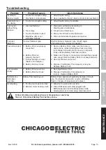
Page 13: ...or wear Switch for example 8 Battery Pack burnt out 1 Remove Battery Pack make sure there are no obstructions reinsert the Battery Pack according to its shape it should only fit one way and press firmly until the Battery Pack locks in place 2 Make sure Charger is connected and operating properly Give enough time for Battery Pack to recharge properly 3 Have technician service tool 4 Dispose of old ...

Page 14: ... not shown 64 500 Nails not shown 65 Hex Key not shown 66 Case not shown Parts List and Diagram PLEASE READ THE FOLLOWING CAREFULLY The manufacturer and or distributor has provided the parts list and assembly diagram in this manual as a reference tool only Neither the manufacturer or distributor makes any representation or warranty of any kind to the buyer that he or she is qualified to make any r...

Page 15: ...call 1 800 444 3353 Item 68993 Safety Operation Maintenance Setup Assembly Diagram 1 2 3 4 5 6 8 7 9 10 14 11 12 13 15 16 51 52 54 55 33 34 35 37 38 39 40 41 43 44 45 46 47 57 22 26 25 23 24 27 42 36 56 53 32 31 30 29 27 28 20 19 17 18 60 59 ...

Page 16: ... the exclusion or limitation of incidental or consequential damages so the above limitation of exclusion may not apply to you This warranty is expressly in lieu of all other warranties express or implied including the warranties of merchantability and fitness To take advantage of this warranty the product or part must be returned to us with transportation charges prepaid Proof of purchase date and...

Reviews: