background image

Page 15

For technical questions, please call 1-800-444-3353.

Item 69454 


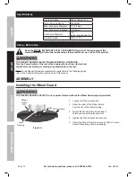
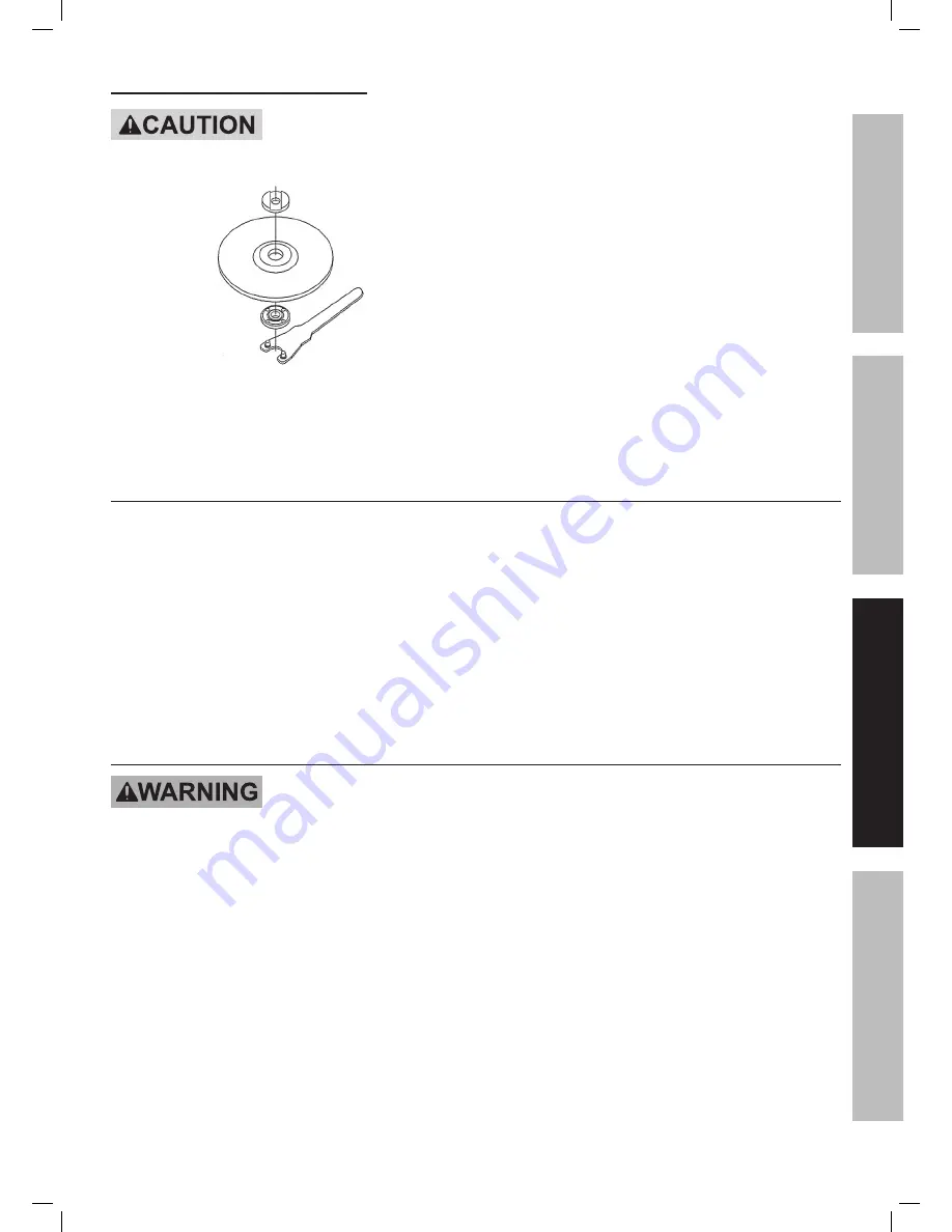
installing a threaded accessory

tO pREVEnt injuRY:  Wear heavy-duty work gloves when handling wire wheels and brushes.   

these accessories are sharp and can cause injury.

Figure E 

1.  The accessory MUST be:

•  rated to at least 7800 RPM.

•  no larger than 7″ (178 mm) in diameter.

•  fitted with a threaded opening of 5/8″ x 11 TPI.

•  undamaged.

•  a sanding disc and backing pad, 

a sanding flap disc, a wire wheel or 

a wire cup brush (accessories not included).

2.  Press in and hold the Spindle Lock Button 

to prevent the Spindle from turning.

3.  Remove the Outer Flange and the 

Inner Flange and keep in a safe place.

4.  Thread disc accessory firmly onto the Spindle.  

Wrench tighten onto the spindle.

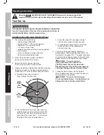
Workpiece and Work area Set up

1.  Designate a work area that is clean and well-lit.  

The work area must not allow access by children 

or pets to prevent distraction and injury.

2.  Route the power cord along a safe route 

to reach the work area without creating a 

tripping hazard or exposing the power cord to 

possible damage.  The power cord must 

reach the work area with enough extra length 

to allow free movement while working.

3.  Secure loose workpieces using a vise or clamps 

(not included) to prevent movement while working.

4.  There must not be hazardous objects, such 

as utility lines or foreign objects, nearby that 

will present a hazard while working.

5.  You must use personal safety equipment including, 

but not limited to, ANSI-approved eye and hearing 

protection, as well as heavy-duty work gloves.

6.  Before beginning work, provide for sparks and 

debris that will fly off the work surface.

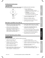
General Operating instructions

tO pREVEnt SERiOuS injuRY:  Grip the tool firmly in both hands.

1.  Make sure that the Trigger is not 

locked on, then plug in the tool.

2.  Squeeze the Trigger to start the tool. 

To lock the tool on, press the Lock ON 

Button then release the Trigger.  

3.  Allow the tool to come up to full speed 

before touching the work material.

4.  Apply the wheel to the work material at a 10° – 15° 

angle, allowing the tool to operate at full speed. 

If the tool bogs down, use lighter pressure.

5.  To create a smoother surface, 

keep the tool moving over the work surface.

6.  Release the Trigger to stop the tool, or press and 

release the Trigger if the Lock ON Button is engaged. 

7.  Allow the tool to come to a complete 

stop before setting it down.

8.  To prevent accidents, turn off the tool and 

disconnect its power supply after use.  Clean, then 

store the tool indoors out of children’s reach.

Sa

FE

tY

Op

ER

ati

O

n

m

aint

Enan

CE

SE

tup

Summary of Contents for 69454

Page 1: ...onally Due to continuing improvements actual product may differ slightly from the product described herein Tools required for assembly and service may not be included When unpacking make sure that the product is intact and undamaged If any parts are missing or broken please call 1 800 444 3353 as soon as possible Save This Manual Keep this manual for the safety warnings and precautions assembly op...

Page 2: ...erate injury Addresses practices not related to personal injury Important Safety Information General Power Tool Safety Warnings Read all safety warnings and instructions Failure to follow the warnings and instructions may result in electric shock fire and or serious injury Save all warnings and instructions for future reference The term power tool in the warnings refers to your mains operated cord...

Page 3: ...attention while operating power tools may result in serious personal injury 2 Use safety equipment Always wear eye protection Safety equipment such as dust mask non skid safety shoes hard hat or hearing protection used for appropriate conditions will reduce personal injuries 3 Prevent unintentional starting Ensure the switch is in the off position before connecting to power source and or battery p...

Page 4: ... these instructions to operate the power tool Power tools are dangerous in the hands of untrained users 5 Maintain power tools Check for misalignment or binding of moving parts breakage of parts and any other condition that may affect the power tool s operation If damaged have the power tool repaired before use Many accidents are caused by poorly maintained power tools 6 Keep cutting tools sharp a...

Page 5: ...ing this test time 7 Wear personal protective equipment Depending on application use face shield safety goggles or safety glasses As appropriate wear dust mask hearing protectors gloves and workshop apron capable of stopping small abrasive or workpiece fragments The eye protection must be capable of stopping flying debris generated by various operations The eye protection must be capable of stoppi...

Page 6: ...uit Interrupter GFCI should also be implemented it prevents sustained electrical shock 23 WARNING Some dust created by power sanding sawing grinding drilling and other construction activities contains chemicals known to the State of California to cause cancer birth defects or other reproductive harm Some examples of these chemicals are Lead from lead based paints Crystalline silica from bricks and...

Page 7: ...nagging 4 Use special care when working corners sharp edges etc Avoid bouncing and snagging the accessory Corners sharp edges or bouncing have a tendency to snag the rotating accessory and cause loss of control or kickback 5 Do not attach a saw chain woodcarving blade or toothed saw blade Such blades create frequent kickback and loss of control Safety Warnings Specific for Grinding and Abrasive Cu...

Page 8: ...kickback Large workpieces tend to sag under their own weight Supports must be placed under the workpiece near the line of cut and near the edge of the workpiece on both sides of the wheel 6 Use extra caution when making a pocket cut into existing walls or other blind areas The protruding wheel may cut gas or water pipes electrical wiring or objects that can cause kickback Safety Warnings Specific ...

Page 9: ... diabetes or Raynaud s Disease should not use this tool If you feel any medical or physical symptoms related to vibration such as tingling numbness and white or blue fingers seek medical advice as soon as possible 2 Do not smoke during use Nicotine reduces the blood supply to the hands and fingers increasing the risk of vibration related injury 3 Wear suitable gloves to reduce the vibration effect...

Page 10: ...e user reducing the risk of electric shock See 3 Prong Plug and Outlet 2 The grounding prong in the plug is connected through the green wire inside the cord to the grounding system in the tool The green wire in the cord must be the only wire connected to the tool s grounding system and must never be attached to an electrically live terminal See 3 Prong Plug and Outlet 3 The tool must be plugged in...

Page 11: ...utdoor use 7 Make sure the extension cord is properly wired and in good electrical condition Always replace a damaged extension cord or have it repaired by a qualified electrician before using it 8 Protect the extension cords from sharp objects excessive heat and damp or wet areas RECOMMENDED MINIMUM WIRE GAUGE FOR EXTENSION CORDS 120 240 VOLT NAMEPLATE AMPERES at full load EXTENSION CORD LENGTH 2...

Page 12: ...nplug the tool from its electrical outlet before assembling or making any adjustments to the tool Note For additional information regarding the parts listed in the following pages refer to the Assembly Diagram near the end of this manual Assembly Installing the Wheel Guard TO PREVENT SERIOUS INJURY Do not operate this tool without the Wheel Guard properly installed Wheel Guard Nut Gear Housing Whe...

Page 13: ...nstalled Alternate locations Auxiliary Handle Figure B 1 The Auxiliary Handle may be installed in one of three positions on either side or on top of the Gear Housing 2 Screw the threaded end of the Auxiliary Handle into the selected position Tighten securely before beginning work Functions Figure C Auxiliary Handle Guard Lock ON Button Trigger Spindle Lock Indicator Light Blade Safety Operation Ma...

Page 14: ... follows a Suspend wheel using a dowel or finger through the arbor hole b Tap Wheel Here 45 45 45 45 Hang Wheel from Dowel V E R T I C A L C E N T E R Tap the flat side of the wheel with a light non metallic object such as a screwdriver handle at a point 45 from the vertical center line on each side of the wheel and 1 2 inches from the edge of the wheel see Illustration c Rotate the wheel 90 and r...

Page 15: ... loose workpieces using a vise or clamps not included to prevent movement while working 4 There must not be hazardous objects such as utility lines or foreign objects nearby that will present a hazard while working 5 You must use personal safety equipment including but not limited to ANSI approved eye and hearing protection as well as heavy duty work gloves 6 Before beginning work provide for spar...

Page 16: ...re misalignment or binding of moving parts cracked or broken parts damaged electrical wiring and any other condition that may affect its safe operation 2 After Use wipe external surfaces of the tool with clean cloth 3 Periodically blow dust and grit out of the motor vents using dry compressed air Wear ANSI approved safety goggles and NIOSH approved breathing protection while doing this 4 WARNING I...

Page 17: ...ecreases over time Carbon brushes worn or damaged Have qualified technician replace brushes Excessive noise or rattling Internal damage or wear Carbon brushes or bearings for example Have technician service tool Overheating 1 Forcing tool to work too fast 2 Blocked motor housing vents 3 Motor being strained by long or small diameter extension cord 1 Allow tool to work at its own rate 2 Wear ANSI a...

Page 18: ...late 1 38 Side Cover right 1 39 Screw St2 9x10 2 40 Rear Cover right 1 41 Brush Holder 2 42 Disc Spring 2 43 Carbon Brush 2 44 Rear Cover left 1 45 Side Cover left 1 46 Power Cord 1 47 Cable Sleeve 1 48 Screw St4 2x14 2 49 Cable Pressplate 1 50 Right Handle 1 51 Trigger 1 52 Power Indicator Lamp 1 53 Indicator Lamp Cover 1 54 Left Handle 1 55 Screw St4 2x16 5 56 Pin Wrench 1 57 Hex Key 1 Parts Lis...

Page 19: ...Page 19 For technical questions please call 1 800 444 3353 Item 69454 Assembly Diagram Safety Operation Maintenance Setup ...

Page 20: ... the exclusion or limitation of incidental or consequential damages so the above limitation of exclusion may not apply to you This warranty is expressly in lieu of all other warranties express or implied including the warranties of merchantability and fitness To take advantage of this warranty the product or part must be returned to us with transportation charges prepaid Proof of purchase date and...

Reviews: