background image

Page 7

For technical questions, please call 1-800-444-3353.

SKU 90599 


permanently mounting the Solar 

panels on a rooftop.

7. 

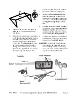
Solar panels (1)

Regulator (2)

lead 

wires

hook-up diagram

Connect the two ring connectors at 

the end of the lead wires coming 

from the 

Solar panels (1)

 to the 

Solar Terminals on the 

Regulator 

(2)

.  See 

FIGuRe 1

. Be sure to 

connect by matching polarities on 

the wires and the 

Regulator (2)

.  

Black (-) is negative and red (+) is 

positive.  Then, connect the wire 

leads so that all of the 

Solar panels 

(1) 

are connected to each other and 

the 

Regulator (2)

 (again, making 

sure you are hooking up to the right 

polarity on the Regulator).  See 

hook-up diagram

, above.

Wiring

note:

 Only a licensed electrician and 

a licensed building contractor can 

safely design and implement a grid 

tie-in system.  Any grid tie-in system 

must meet all applicable building 

and electrical codes, and must meet 

standards established by the area 

power company.

1.  Run wires from the panels, through 

weatherproof grommets and into 

the enclosure where the charge 

controller/regulator is located.  Use 

wires of the proper size and rating.

2.  Connect to charge controller/regulator 

according to controller/regulator’s 

instructions.

3.  Secure all connections using 

terminals, or solder all wire splices to 

ensure good connections.

4.  Weatherproof all connections.

OpeRATIOn

note:  

Performance of the Solar Panels 

will vary dependent on site location, 

angle of the panels in relation to the 

arc of the sun, and available sunlight.

Recharging a Battery

1.  To recharge a 12 volt battery (not 

included), while paying attention 

to the proper polarity (black (-) is 

negative and red (+) is positive), 

connect the two ring terminals on 

the 

Battery connector (3)

 to the 

Battery Terminals on the back of 

the 

Regulator (2)

.  See 

FIGuRe 

1

.  Then, connect the black clamp to 

the black or negative (-) terminal on 

the battery (not included).  Finally, 

connect the red clamp to the red or 

positive (+) terminal on the battery.  

Avoid accidental contact of the red 

and black battery clamps to each 

other.

note:

  Do not change the order explained 

in number 1 above or electric shock 

resulting in serious injury or death 

may occur.

2.  Turn on the Regulator. See the On/

Off switch in 

FIGuRe 1

 on page 6.

3.  Never leave the battery (not included) 

unattended while charging.  When 

the battery (not included) is fully 

charged, the reading on the voltage 

display will show “13” or above.  

Note: the voltage display will have to 

be turned on in order to monitor the 

Summary of Contents for 90599 and

Page 1: ...reserved No portion of this manual or any artwork contained herein may be reproduced in any shape or form without the express written consent of Harbor Freight Tools Diagrams within this manual may n...

Page 2: ...t symbol indicates a hazardous situation which if not avoided could result in minor or moderate injury NOTICE is used to address practices not related to personal injury CAUTION without the safety ale...

Page 3: ...s rated output Increase output ratings by 25 when determining component required voltage and amperage ratings Refer to Section 690 8 of the National Electrical Code for an additional multiplying facto...

Page 4: ...vice Precautions 1 Before service maintenance or cleaning a Dry solar panels and outdoor wiring thoroughly while wearing electrically insulated gloves b Cover all solar panels with an opaque cover suc...

Page 5: ...Assembly Diagram near the end of this manual Location 1 Locate the panel where it will receive full unobstructed sunlight especially during midday Nearby trees or tall plants will drop debris requirin...

Page 6: ...d provide enough ventilation to allow the unit to vent and cool properly 4 Secure the Frame Assembly 6a 6d to its mounting location using hardware not supplied through the four holes on the bottom of...

Page 7: ...troller regulator according to controller regulator s instructions 3 Secure all connections using terminals or solder all wire splices to ensure good connections 4 Weatherproof all connections Operati...

Page 8: ...too high above 14 5 volts the Regulator 2 will automatically shut off power input to prevent damage to the battery not included c Overload Protection If the output current exceeds 4 amps the fuse See...

Page 9: ...olar panels d Disconnect all batteries To prevent serious injury from electric shock or cuts Do not use damaged solar panel If wiring insulation is damaged or weathered glass is cracked or housing is...

Page 10: ...and maintain batteries according to supplier s instructions Adjustment To Increase Efficiency 7 In the Winter increase the panel s angle by 10 8 In the Summer decrease the angle by up to 10 9 In the...

Page 11: ...certified and licensed technicians and not by the buyer The buyer assumes all risk and liability arising out of his or her repairs to the original product or replacement parts thereto or arising out o...

Reviews: