SKU 91213
PAGE 11
5.
Place the Generator as close as possible to the electrical tools and equipment
being powered to reduce the length of extension cords.
6.
If the Generator in located indoors the Engine exhaust must be ventilated to the
outdoors using leak-proof, heat resistant, flexible, metal, flex tubing.
GENERATOR SUPPORT AND MOUNTING
1.
Mount the Generator on a concrete slab capable of supporting the weight of the
Generator. The slab must extend on all sides beyond the Frame (41) by at least
one foot. Contact a cement contractor for slab specifications if necessary. Attach
the Frame to the concrete slab using 3/8” diameter expansion anchor bolts (not
supplied).
GROUNDING THE GENERATOR
1.
NOTE:
It is recommended that only a trained and licensed electrician perform
this procedure.
OPERATING INSTRUCTIONS
NOTE:
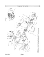
For additional references to the parts listed in the following pages, refer to the
Assembly Diagrams
on pages 19 and 21.
Pre-Start Checks:
1.
Check to make sure the Engine’s Power Switch (2) is in its
“OFF”
position.
(See Figure B, next page.)
2.
Connect a #6 AWG grounding wire (not included) from the Ground Connector (8)
on the Generator to a grounding rod (not included) that has been driven at least
24 inches deep into the earth. The grounding rod must be an earth-driven cop-
per or brass rod (electrode) which can adequately ground the Generator.
(See Figure B, next page.)
2.
IMPORTANT ! Prior to first using the Generator, the Engine MUST be filled
with approximately 3/4 (0.63) quart of a high quality SAE 10W-30 grade
engine oil.
To do so, unscrew and remove the Engine’s Oil Dipstick (65A) lo-
cated at the bottom of the Engine Crankcase. Fill the Engine’s Crankcase until
the oil level is level with
the
upper marked line
on the Dipstick. Then, screw the
Dipstick back into the Oil Fill Hole.
(See Figure C, next page.)
Summary of Contents for 91213
Page 19: ...SKU 91213 PAGE 19 ...


