background image

Page 10

For technical questions, please call 1-800-444-3353.

SKU 91222

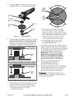
Installing a Threaded Accessory


TO PREVENT INJURY: Wear heavy-duty work gloves 

when handling wire wheels and brushes.  These 

accessories are sharp and can cause injury.

1.  The accessory MUST be:

•  rated to at least 11,000 RPM.

•  no larger than 4″ in diameter.

•  fitted with a threaded opening of  

5/8″ x 11 TPI.

•  undamaged.

•  a sanding disc and backing pad, a sanding 

flap disc, a wire wheel or a wire cup 

brush (accessories not included).

2.  Press in and hold the LOCK PIN (12) to 

prevent the Spindle from turning.

3.  Remove the Outer Flange and the Inner 

Flange and keep in a safe place.

4.  Thread disc accessory firmly onto the 

Spindle.  Wrench tighten onto the spindle.

Work Piece and Work 

Area Set Up

1.  Designate a work area that is clean and well-lit.  

The work area must not allow access by children 

or pets to prevent distraction and injury.

2.  Route the power cord along a safe route to reach 

the work area without creating a tripping hazard or 

exposing the power cord to possible damage.  The 

power cord must reach the work area with enough 

extra length to allow free movement while working.

3.  Secure loose work pieces using a vise or clamps 

(not included) to prevent movement while working.

4.  There must not be hazardous objects, such 

as utility lines or foreign objects, nearby that 

will present a hazard while working.

5.  You must use personal safety equipment including, 

but not limited to, ANSI-approved eye and hearing 

protection, as well as heavy-duty work gloves.

6.  Before beginning work, provide for sparks and 

debris that will fly off the work surface.

General Operating Instructions


TO PREVENT SERIOUS INJURY: Grip the tool firmly 

with both hands.

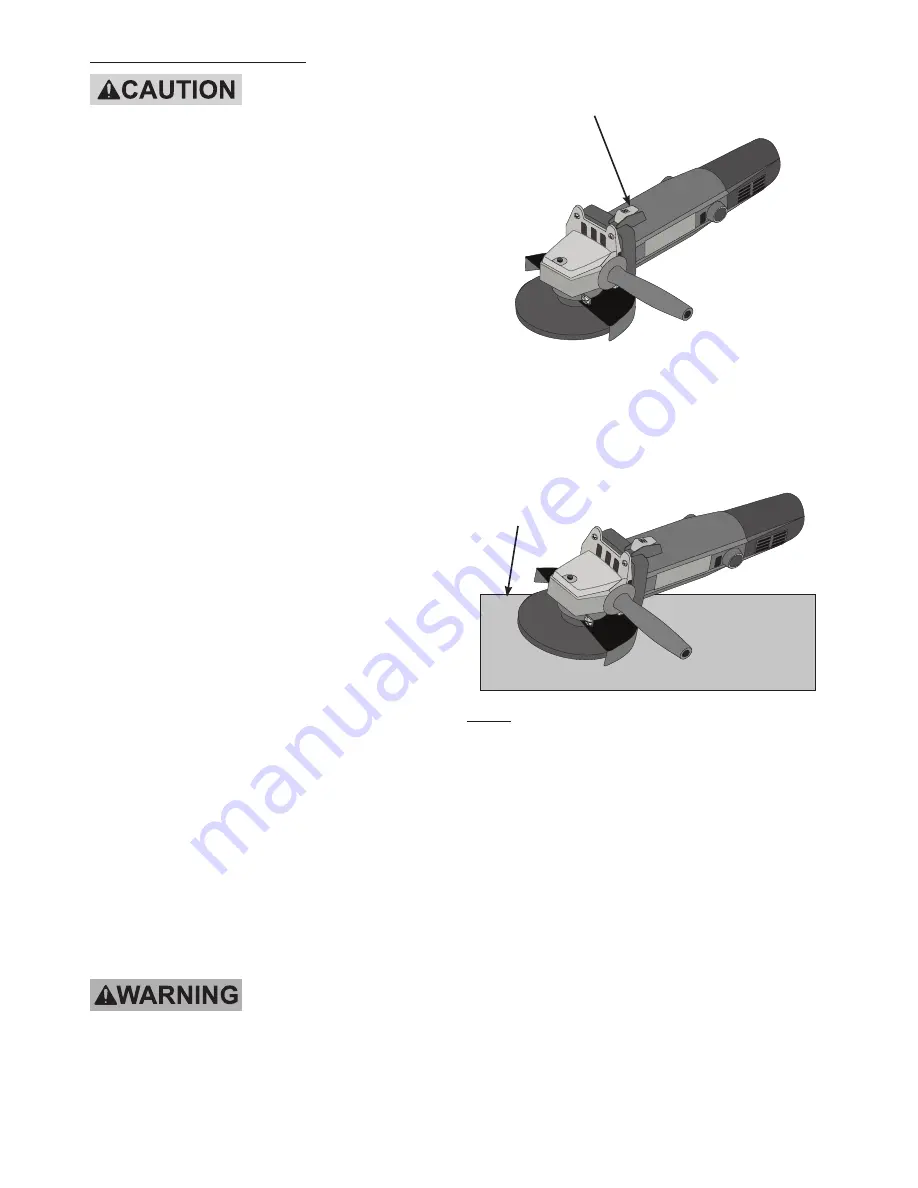
1.  Make sure that the SLIDE SWITCH (19) 

is not locked on, then plug in the tool.

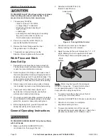
2.  Slide the SLIDE SWITCH (19) 

forward to start the tool.

Figure 4 - Turning ON the Grinder

Slide Switch 

(19)

3.  Allow the tool to come up to full speed 

before touching the work material.

4.  Apply the wheel to the work material at a 10° – 15° 

angle, allowing the tool to operate at full speed. 

If the tool bogs down, use lighter pressure.

Work 

Surface

NOTE:


Motor may heat up with the prolonged 

medium to heavy use.  To avoid motor burnout, 

do not operate beyond a 15 to 20 minute 

duty cycle when using heavy force.

5.  To create a smoother surface, keep the tool 

moving over the work surface.

6.  Slide the SLIDE SWITCH (19) back to stop the tool. 

7.  Allow the tool to come to a complete 

stop before setting it down.

8.  To prevent accidents, turn off the tool and 

disconnect its power supply after use.  Clean, then 

store the tool indoors out of children’s reach.

Summary of Contents for 91222

Page 1: ...orfreight com Email our technical support at tech harborfreight com Copyright 2004 by Harbor Freight Tools All rights reserved No portion of this manual or any artwork contained herein may be reproduced in any shape or form without the express written consent of Harbor Freight Tools Diagrams within this manual may not be drawn proportionally Due to continuing improvements actual product may differ...

Page 2: ...ery operated cordless power tool 1 Work area safety a Keep work area clean and well lit Cluttered or dark areas invite accidents b Do not operate power tools in explosive atmospheres such as in the presence of flammable liquids gases or dust Power tools create sparks which may ignite the dust or fumes c Keep children and bystanders away while operating a power tool Distractions can cause you to lo...

Page 3: ...unfamiliar with the power tool or these instructions to operate the power tool Power tools are dangerous in the hands of untrained users e Maintain power tools Check for misalignment or binding of moving parts breakage of parts and any other condition that may affect the power tool s operation If damaged have the power tool repaired before use Many accidents are caused by poorly maintained power t...

Page 4: ... draw the dust inside the housing and excessive accumulation of powdered metal may cause electrical hazards 15 Do not operate the power tool near flammable materials Sparks could ignite these materials 16 Do not use accessories that require liquid coolants Using water or other liquid coolants may result in electrocution or shock 17 Maintain labels and nameplates on the tool These carry important s...

Page 5: ... loss of control Safety Warnings Specific for Grinding Operations 1 Use only wheel types that are recommended for your power tool and the specific guard designed for the selected wheel Wheels for which the power tool was not designed cannot be adequately guarded and are unsafe 2 The guard must be securely attached to the power tool and positioned for maximum safety so the least amount of wheel is ...

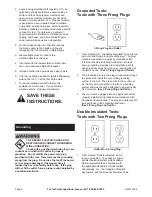
Page 6: ...power cord plug provided with the tool Never remove the grounding prong from the plug Do not use the tool if the power cord or plug is damaged If damaged have it repaired by a service facility before use If the plug will not fit the outlet have a proper outlet installed by a qualified electrician Grounded Tools Tools with Three Prong Plugs 3 Prong Plug and Outlet 1 Tools marked with Grounding Requ...

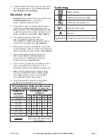
Page 7: ... you are using one extension cord for more than one tool add the nameplate amperes and use the sum to determine the required minimum cord size See Table A 6 If you are using an extension cord outdoors make sure it is marked with the suffix W A W in Canada to indicate it is acceptable for outdoor use 7 Make sure the extension cord is properly wired and in good electrical condition Always replace a ...

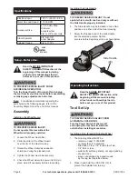
Page 8: ...the planned work 4 Tighten the Wheel Guard Nut securely 5 Check the Wheel Guard to ensure it is firmly in place Adjust if necessary before proceeding Installing the Side Handle TO PREVENT SERIOUS INJURY Do not operate this tool with one hand only or without the Side Handle properly installed 6 The Side Handle may be installed in one of two positions on either side of the Gear Housing 7 Screw the t...

Page 9: ...he wheel with a light non metallic object such as a screwdriver handle at a point 45 from the vertical center line on each side of the wheel and 1 2 inches from the edge of the wheel see Illustration c Rotate the wheel 90 and repeat the test until the entire wheel has been checked d An undamaged wheel will give a clear tone If cracked there will be a dead sound and not a clear ring 6 For wheels wi...

Page 10: ...d to prevent movement while working 4 There must not be hazardous objects such as utility lines or foreign objects nearby that will present a hazard while working 5 You must use personal safety equipment including but not limited to ANSI approved eye and hearing protection as well as heavy duty work gloves 6 Before beginning work provide for sparks and debris that will fly off the work surface Gen...

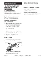
Page 11: ...clean cloth 3 Periodically blow dust and grit out of the motor vents using dry compressed air Wear ANSI approved safety goggles and NIOSH approved breathing protection while doing this 4 WARNING If the supply cord of this power tool is damaged it must be replaced only by a qualified service technician Carbon Brush Replace the carbon brush when it wears down to about 3 16 5 mm or sparking will occu...

Page 12: ...y goggles and NIOSH approved dust mask respirator while blowing dust out of motor using compressed air 3 Eliminate use of extension cord If an extension cord is needed use one with the proper diameter for its length and load See Extension Cords in GROUNDING section Tool does not grind sand or brush effectively 1 Disc accessory may be loose on Spindle Check tightness of Outer Flange Arbor Nut or th...

Page 13: ...in 1 13 Pinion 1 14 Ball Bearing 1 15 Armature 1 Part Description Qty 16 Ball Bearing 1 17 Stator 1 18 Housing 1 19 Slide Switch 1 20 Slide Bar 1 21 Brush Holder 1 22 Carbon Brush 1 23 Brush Cap 1 24 Cord 1 25 Cover 1 26 Switch 1 27 Switch Holder 1 28 Wrench 1 29 Side Handle 1 29 Record Product s Serial Number Here Note If product has no serial number record month and year of purchase instead Note...

Page 14: ...ental or consequential damages so the above limitation of exclusion may not apply to you THIS WARRANTY IS EXPRESSLY IN LIEU OF ALL OTHER WARRANTIES EXPRESS OR IMPLIED INCLUDING THE WARRANTIES OF MERCHANTABILITY AND FITNESS To take advantage of this warranty the product or part must be returned to us with transportation charges prepaid Proof of purchase date and an explanation of the complaint must...

Page 15: ......

Page 16: ...3491 Mission Oaks Blvd PO Box 6009 Camarillo CA 93011 800 444 3353 ...

Reviews: