background image

Page 10

For technical questions, please call 1-800-444-3353.

SKU 93213 


OPERATION

WARNINg!

  Unplug the unit before adjusting 

chain to be sharpened.

Refer to the Assembly Drawing on page 10 and 

the various photographs.

Note:

 Raise the Top Housing (4B) while 

adjusting the chain.
Clean the chain before sharpening.  

1. 

Wash it with a nonflammable solvent. Do 

not use gasoline.  Dry the chain.

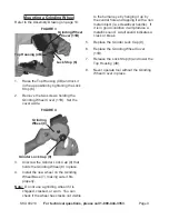
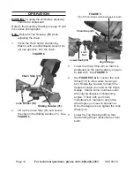
FIguRE 6

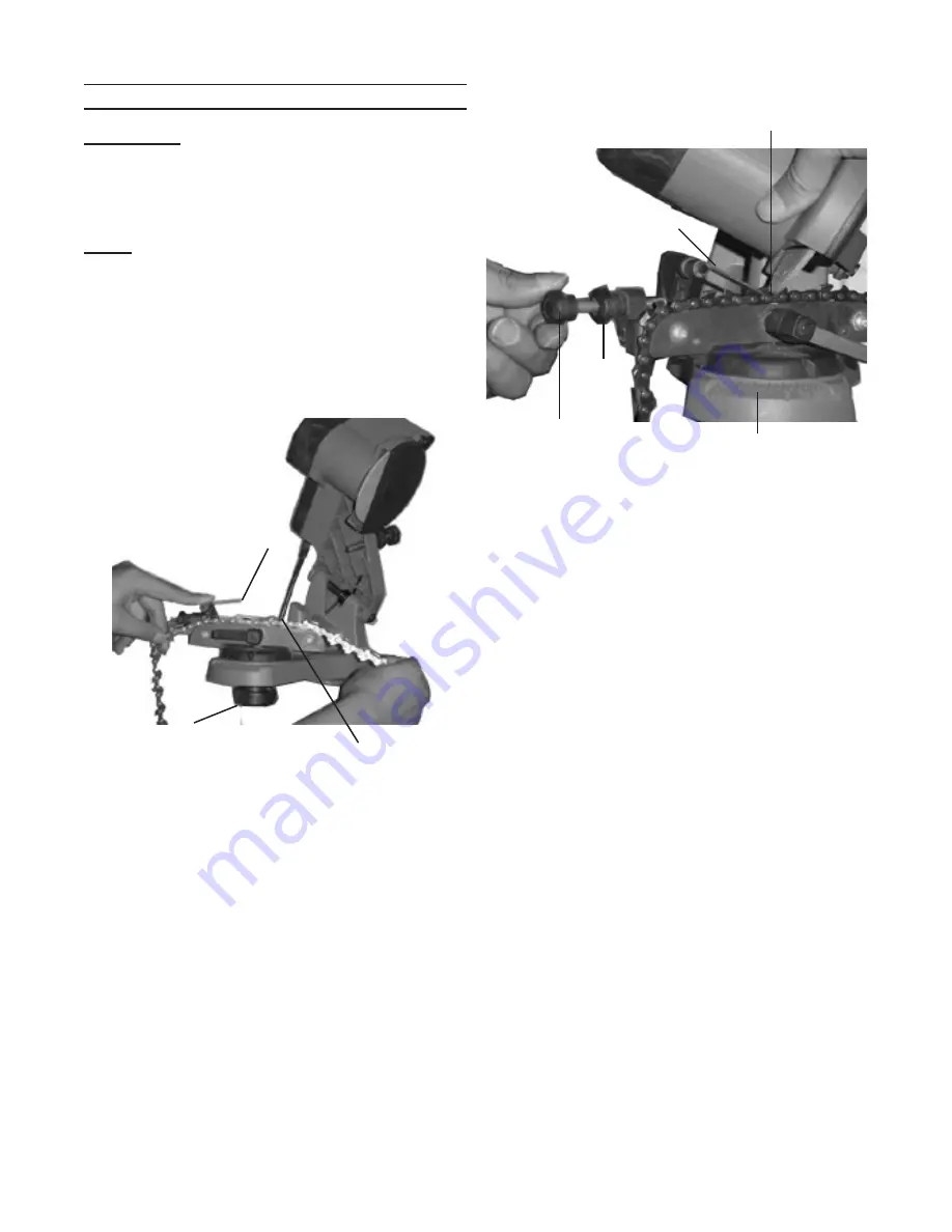
Chain Stop (23)

Sliding guides (31)

Lock Wheel (18)

2.  Lift up the Chain Stop (23) and secure 

the chain in the Sliding Guides (31).  See 

FIguRE 6

.

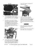
FIguRE 5

Chain Stop (23)

Tip of Chain Stop positioned against tooth.

Angle gauge

Lower Knob (26)

Lock 

Nut

3.  Lower the Chain Stop (23) so that it is 

positioned on the tooth (cutter) you want 

to start with.  See 

FIguRE 5

.

See 

4. 

FIguRES 5 & 6

.  Loosen the Lock 

Wheel (18) to allow entire housing to 

turn. Rotate the housing to match the 

degree of angle you need on the Angle 

Gauge.  Chains come in various sizes 

with varying degrees of sharpening 

angles.  Check with your chain 

manufacturer’s manual to determine 

what degree you need to sharpen at.  

Once the degree is set, tighten the Lock 

Wheel (18).
Lower the Top Housing (4B) so that 

5. 

the Grinding Wheel (8) skims the chain 

tooth. 

Summary of Contents for 93213

Page 1: ... reserved No portion of this manual or any artwork contained herein may be reproduced in any shape or form without the express written consent of Harbor Freight Tools Diagrams within this manual may not be drawn proportionally Due to continuing improvements actual product may differ slightly from the product described herein Tools required for assembly and service may not be included For technical...

Page 2: ...ch if not avoided could result in minor or moderate injury NOTICE is used to address practices not related to personal injury CAUTION without the safety alert symbol is used to address practices not related to personal injury Safety Warnings and Precautions WARNING When using tool basic safety precautions should always be followed to reduce the risk of personal injury and damage to equipment Read ...

Page 3: ...aged parts 14 Before using any tool any part that appears damaged should be carefully checked to determine that it will operate properly and perform its intended function Check for alignment and binding of moving parts any broken parts or mounting fixtures and any other condition that may affect proper operation Any part that is damaged should be properly repaired or replaced by a qualified techni...

Page 4: ...a nonmetallic object ie screwdriver handle If it is in good condition it will produce a metallic sound A dull sound indicates a crack or break Only use grinding wheels that fit the 2 Arbor 7 8 Do not try to change or modify the mounting hole on a grinding wheel to make it fit Grinding wheel replacements are available at Harbor Freight Tools Do not overtighten the Grinder Lock Cap 3 9 Hand tighten ...

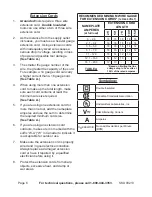
Page 5: ...the user reducing the risk of electric shock See 3 Prong Plug and Outlet The grounding prong in the plug is 2 connected through the green wire inside the cord to the grounding system in the tool The green wire in the cord must be the only wire connected to the tool s grounding system and must never be attached to an electrically live terminal See 3 Prong Plug and Outlet The tool must be plugged in...

Page 6: ...eplate amperes and use the sum to determine the required minimum cord size See Table A If you are using an extension cord 6 outdoors make sure it is marked with the suffix W A W in Canada to indicate it is acceptable for outdoor use Make sure the extension cord is properly 7 wired and in good electrical condition Always replace a damaged extension cord or have it repaired by a qualified electricia...

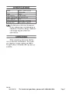
Page 7: ... Dimensions 4 1 4 Dia x 1 8 Thick Working time S3 10S ON 15S OFF Note Performance of this tool if powered by line voltage may vary depending on variations in local line voltage Extension cord usage may also affect tool performance Unpacking When unpacking make sure that the item is intact and undamaged If any parts are missing or broken please call Harbor Freight Tools at 1 800 444 3353 as soon as...

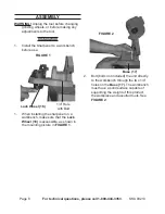
Page 8: ...use FIGURE 1 1 4 Hole with Bolt Lock Wheel 18 1 When installing the sharpener on a workbench make sure that the Lock Wheel 18 is accessible as shown in the mounting picture in FIGURE 1 Base 17 FIGURE 2 2 Bolt bolts not included the unit directly to the workbench through the two 1 4 holes on the Base 17 The workbench must have a solid surface capable of supporting the weight of this product the wor...

Page 9: ... that holds the Grinding Wheel 8 in place Install the new wheel on the Grinding 4 Wheel Base 7 making sure it fits properly Note Do not use a grinding wheel if it is chipped cracked or worn You can check if the wheel has cracks not visible to the human eye by hanging it up by the central hole and tapping it with a non metal object ie screwdriver handle If it is in good condition it will produce a ...

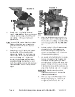
Page 10: ...he Sliding Guides 31 See FIGURE 6 FIGURE 5 Chain Stop 23 Tip of Chain Stop positioned against tooth Angle Gauge Lower Knob 26 Lock Nut 3 Lower the Chain Stop 23 so that it is positioned on the tooth cutter you want to start with See FIGURE 5 See 4 FIGURES 5 6 Loosen the Lock Wheel 18 to allow entire housing to turn Rotate the housing to match the degree of angle you need on the Angle Gauge Chains ...

Page 11: ...8 Handle 34 Limiting Gauge 8 Lock the chain in the Sliding Guides 31 by turning the Handle 34 See FIGURE 8 The Handle 34 should be situated so that you can easily release and tighten it You will need to release it each time you move to the next link and tighten it to sharpen each link FIGURE 9 9 If the chain has been repeatedly sharpened the chain depth limiting gauges may need to be taken down wi...

Page 12: ...ed all of the links set up for this angle FIGURE 11 Lock Wheel 18 5 After you finished sharpening all of the teeth set for your current angle turn off the machine by pushing the Switch 5B and unplugging the unit See FIGURE 11 Loosen the Lock Wheel 18 and reset 6 the angle so that the first tooth that hasn t been sharpened is positioned against the Chain Stop 23 and locked in as explained on page 6...

Page 13: ... t damaged Do not use a grinding wheel if it is chipped cracked or worn You can check if the wheel has cracks not visible to the human eye by hanging it up by the central hole and tapping it with a non metal object ie screwdriver handle If it is in good condition it will produce a metallic sound A dull sound indicates a crack or break Replace the Grinding Wheel when it 3 grinds down to a diameter ...

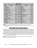
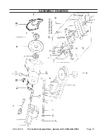
Page 14: ...It includes all part numbers with asterisks Part numbers with asterisks 19 through 36 are not available individually PLEASE READ THE FOLLOWING CAREFULLY THE MANUFACTURER AND OR DISTRIBUTOR HAS PROVIDED THE PARTS DIAGRAM IN THIS MANUALAS A REFERENCE TOOL ONLY NEITHER THE MANUFACTURER NOR DISTRIBUTOR MAKES ANY REPRESENTA TION OR WARRANTY OF ANY KIND TO THE BUYER THAT HE OR SHE IS QUALIFIED TO MAKE A...

Page 15: ...Page 15 For technical questions please call 1 800 444 3353 SKU 93213 Assembly Drawing Chain Mounting Assembly Set 39 ...

Page 16: ...ncidental or consequential damages so the above limitation of exclusion may not apply to you This warranty is expressly in lieu of all other warranties express or implied including the warranties of merchantability and fitness To take advantage of this warranty the product or part must be returned to us with transportation charges prepaid Proof of purchase date and an explanation of the complaint ...

Reviews: