background image

SKU 93632

For technical questions, please call 1-800-444-3353.

English

Page 8

OPERATING INSTRUCTIONS

Your Low Speed Heavy-duty Drill will usually be preassembled. In some cases, due to variations in packaging,
you may have to install the Spade Handle and Auxiliary Handle. Please refer to the assembly diagram on page
10.

CAUTION: Be sure the tool is unplugged from any power source before performing any installation

or adjustment of the tool.

1.

Align the Spade Handle (31) with the Back Case (32). Insert the Spade Handle Knob (30) through the
Spade Handle into the Back Case. Tighten the Spade Handle Knob by turning clockwise until tight.

2.

Insert the Screw (14) through the Side Handle (15). Position the Side Handle on the Gear Housing Cover
(22). Using a screwdriver (not included) tighten the Screw (14) until tight.

NOTE: Periodically check to be sure the handles remain tight. Never try to reposition the handles while
the tool is running.

About Low Speed Heavy-duty Drills:

While an extremely useful tool, heavy-duty drills can be dangerous if used improperly or in damaged
condition.

1.

This tool incorporates a double gear reduction transmission to reduce drill speed while increasing torque.
This design improves performance when drilling large holes up to 2” in wood and 1/2” in mild steel. This
feature also helps prevent the tool from “bogging down” or stopping when under heavy load.

2.

Drill Bits (not included) come in various sizes and types. Various types include low and high speed twist
bits for metals, spade or brad point bits for wood, forstner bits for flat bottomed holes in wood or plastic,
auger bits for boring through walls and floors, masonry bits for plaster and dry wall, etc. Always select the
proper bit type and size for the application at hand.

3.

This drill can use drill bit shank sizes between 1/16” and 1/2” inclusive. Boring hole size may be larger
than the shank size. Do not attempt to use drill bits larger or smaller than this range.

4.

Whenever installing a drill bit into the tool, first unplug the tool. By hand, rotate the outer ring of the Chuck
counterclockwise to open it enough to allow the bit to be inserted. Be sure the bit is centered in the
Chuck. By hand, rotate the outer ring of the Chuck clockwise to tighten on the bit. Check to be sure the
bit is centered in the jaws of the Chuck.

5.

Insert the tip of the Chuck Key into one of the openings drilled into the side of the Chuck. Engage the
gears of the Chuck Key with the gear teeth on the outside of the Chuck. Turn the Chuck Key clockwise to
tighten the jaws of the Chuck firmly on the drill bit.  CAUTION: Be sure the drill bit is centered and firmly
fixed in the Chuck before beginning work.

Power Switch Features

Note: The Power Switch (46) has a variable speed feature.  Simply turn the dial below the Power Switch
to adjust the drill speed.  The dotted lines on the dial are spaced from narrow to wide to indicate increasing
drill speed.

Note:  The trigger lock button on the Power Switch, when activated, will allow the drill to run without
continuous finger pressure on the power switch.  To release the trigger lock, simply press your finger on
the power switch.

1.

Do not start the tool until you have observed all safety preparations and are ready to work.

Summary of Contents for 93632

Page 1: ... slightly from the product described herein 3491 Mission Oaks Blvd Camarillo CA 93011 Visit ourWeb site at http www harborfreight com Copyright 2006 by Harbor Freight Tools All rights reserved No portion of this manual or any artwork contained herein may be reproduced in any shape or form without the express written consent of Harbor FreightTools For technical questions and replacement parts pleas...

Page 2: ...e to follow all instructions listed below may result in electric shock fire and or serious injury SAVETHESE INSTRUCTIONS WORK AREA 1 Keep your work area clean and well lit Cluttered benches and dark areas invite accidents 2 Do not operate power tools in explosive atmospheres such as in the presence of flammable liquids gases or dust Power tools create sparks which may ignite the dust or fumes 3 Ke...

Page 3: ...esult in personal injury 14 Do not overreach Keep proper footing and balance at all times Proper footing and balance enables better control of the power tool in unexpected situations 15 Use safety equipment Always wear eye protection Dust mask nonskid safety shoes hard hat or hearing protection must be used for appropriate conditions TOOL USE AND CARE 16 Use clamps not included or other practical ...

Page 4: ...g workspace Always keep the work area free of obstructions grease oil trash and other debris Do not use a power tool in areas near flammable chemicals dusts and vapors Do not use this product in a damp or wet location 5 When using a handheld power tool always maintain a firm grip on the tool with both hands to resist starting torque Always have one hand on the Handle and the other either on the Sp...

Page 5: ...quipment such as those dust masks that are specially designed to filter out microscopic particles California Health Safety Code 25249 5 et seq GROUNDING WARNING Improperly connecting the grounding wire can result in the risk of electric shock Check with a qualified electrician if you are in doubt as to whether the outlet is properly grounded Do not modify the power cord plug provided with the tool...

Page 6: ... Diagram B DIAGRAM B EXTENSION CORDS 1 Grounded tools require a three wire extension cord Double Insulated tools can use either a two or three wire extension cord 2 As the distance from the supply outlet increases you must use a heavier gauge extension cord Using extension cords with inadequately sized wire causes a serious drop in voltage resulting in loss of power and possible tool damage See Di...

Page 7: ...properly wired and in good electrical condition Always replace a damaged extension cord or have it repaired by a qualified electrician before using it 8 Protect your extension cords from sharp objects excessive heat and damp or wet areas S D R O C N O I S N E T X E R O F E G U A G E R I W M U M I N I M D E D N E M M O C E R E T A L P E M A N S E R E P M A d a o L l l u F t A H T G N E L D R O C N ...

Page 8: ...int bits for wood forstner bits for flat bottomed holes in wood or plastic auger bits for boring through walls and floors masonry bits for plaster and dry wall etc Always select the proper bit type and size for the application at hand 3 This drill can use drill bit shank sizes between 1 16 and 1 2 inclusive Boring hole size may be larger than the shank size Do not attempt to use drill bits larger ...

Page 9: ...being observed Be sure to wear ANSI approved eye protection NOTE The motor will heat up as it is used To avoid motor burn out do not use continually for more than 20 minutes at a time Allow the tool to cool down for at least 10 minutes before resuming work 1 Place the drill tip on the work piece and Start the tool 2 Apply light pressure on the tool to help it drill into the workpiece Do not overlo...

Page 10: ...2 r e v o C g n i s u o H r a e G 1 0 5 Z 2 0 0 0 6 g n i r a e B l l a B 1 3 2 0 1 m p i l c r i C 1 1 5 g n i R O 1 4 2 r e n i a t e R g n i r a e B 1 2 5 g n i R l a e S 1 5 2 e r u t a m r A 1 3 5 r a e G t s r i F 1 6 2 7 2 8 0 6 g n i r a e B l l a B 1 4 5 t f a h S t s r i F 1 7 2 g n i h s u B g n i r a e B 1 5 5 t e k s a G 1 8 2 e d i u G g n i d n i W 1 NOTE Some parts are listed and s...

Page 11: ...KINDTO THE BUYERTHAT HE OR SHE IS QUALIFIEDTO MAKE ANY REPAIRS TO THE PRODUCT ORTHAT HE OR SHE IS QUALIFIEDTO REPLACE ANY PARTS OFTHE PRODUCT IN FACT THE MANUFACTURER AND OR DISTRIBUTOR EXPRESSLY STATES THAT ALL REPAIRS AND PARTS REPLACE MENTS SHOULD BE UNDERTAKEN BY CERTIFIED AND LICENSED TECHNICIANS AND NOT BY THE BUYER THE BUYER ASSUMES ALL RISK AND LIABILITY ARISING OUT OF HIS OR HER REPAIRS T...

Page 12: ... harborfreight com Le copyright 2006 par le Harbor Freight Tools Tous droits réservés Aucune portion de ce manuel ou de n importe quel travail d art contenu ici ne peut être reproduite dans aucune forme ou formulaire sans le consentement rapidement écrit de Harbor Freight Tools Pour les questions techniques et les pièces détachées appelez vous s il vous plaît 1 800 444 3353 93632 IMPORTANT Cette é...

Page 13: ...re dans un coffre fort et un endroit sec pour la référence future RÈGLES RÉPANDUES DE SÉCURITÉ AVERTISSEMENT LISEZ ET COMPRENEZTOUTES LES INSTRUCTIONS L échec de suivre toutes les instructions énumérées peut ci dessous s ensuivre dans le décharge électrique le feu et ou la blessure sérieuse SAUVEZ CES INSTRUCTIONS RÉGION DE TRAVAIL 1 Garder votre région de travail propre et bien allumé Les bancs e...

Page 14: ...tilisez le sens commun en faisant marcher un instrument de pouvoir N utilisez pas d instrument de pouvoir pendant que fatigué ou sous l influence de drogues alcool ou médication Un moment d inattention en faisant marcher des instruments de pouvoir peut s ensuivre dans la blessure personnalisée sérieuse 11 Robe correctement N usez pas de vêtements desserrés ou de bijouterie Contenez de longs cheveu...

Page 15: ... 24 L entretien d instrument doit être exécuté seulement par le personnel de réparation qualifié L entretien ou la maintenance exécutée par le personnel disqualifié pourraient s ensuivre dans un risque de blessure 25 En assurant l entretien d un instrument utilisez des pièces détachées seulement identiques Suivez des instructions dans la Inspection la Maintenance Et la section Nettoyante de ce man...

Page 16: ...le moment de torsion de foreuse peut causer la blessure 15 AVERTISSEMENT Les gens avec les stimulateurs cardiaques devraient consulter leur docteur s avant le fait d utiliser ce produit Les champs électromagnétiques dans la proche proximité à un stimulateur cardiaque du cœur pourraient causer l interférence à ou l échec du stimulateur cardiaque En plus les gens avec les stimulateurs cardiaques dev...

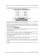
Page 17: ...e courant doit être raccordée à une prise de courant correctement mise à la terre Si l instrument devrait électriquement mal fonctionner ou se décomposer installer à la terre fournit un sentier de résistance bas pour emporter l électricité de l utilisateur en réduisant le risque de décharge électrique Voir le Diagramme A 2 La dent d installer à la terre dans la prise de courant est raccordée par l...

Page 18: ... le Diagramme C la page suivante 3 Plus petit le nombre de calibre du fil plus grand la capacité du cordon Par exemple un 14 cordon de calibre peut porter un plus haut courant qu un 16 cordon de calibre Voir le Diagramme C 4 En utilisant plus qu un cordon d extension pour créer la longueur totale assurez vous que chaque cordon contient au moins la grandeur métallique minimale exigée Voir le Diagra...

Page 19: ...mporte quelle source de pouvoir avant le fait d exécuter n importe quelle installation ou ajustage de l instrument S D R O C N O I S N E T X E L R U O P É D N A M M O C E R L A M I N I M E U Q I L L A T É M E R B I L A C E L E U Q A L P S E R È P M A e g r a h C e n i e l P a l À N O I S N E T X E D N O D R O C E D R U E U G N O L m 5 7 m 5 1 m 5 2 2 m 0 3 m 5 4 0 2 0 8 1 8 1 8 1 8 1 6 1 4 3 1 2 8...

Page 20: ...ourner l anneau extérieur de Mandrin en sens inverse des aiguilles d une montre pour l ouvrir assez pour permettre au morceau d être insérés Soyez sûrs que le morceau est centré dans Mandrin À la main faites tourner l anneau extérieur de Mandrin dans le sens des aiguilles d une montre pour vous serrer sur le morceau Vérifiez pour être sûr que le morceau est centré dans les mâchoires de Mandrin 5 I...

Page 21: ...de 20 minutes à la fois Permettez à l instrument de refroidir depuis au moins 10 minutes avant le travail reprenant 1 Placer le bout de foreuse sur le morceau de travail et Commencer l instrument 2 Appliquer la pression douce sur l instrument pour l aider à forer dans la pièce de fabrication Ne surchargez pas l instrument Si la vitesse ralentit manifestement n appuyez pas sur la foreuse comme dure...

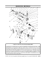
Page 22: ... d n o R 4 9 2 r o t a t S 1 2 0 5 5 x 5 T S s i V 4 0 3 e h c ê B e d e é n g i o P e d n o t u o B 1 3 y e K n i r d n a M 1 1 3 e h c ê B e d e é n g i o P 1 4 2 2 x 6 m t e n n o B e d e t ê T e d s i V 1 2 3 s a C e r è i r r A 1 5 n i r d n a M 1 3 3 i a l a B e d t e n n o B 2 6 1 2 m e l l e d n o R 1 4 3 e n o b r a C e d i a l a B 2 7 e g a n e r g n E d n o i t a t i b a H 1 5 3 i a l a...

Page 23: ...E SORTE À L ACHETEUR QU IL OU ELLE EST AUTORISÉ POUR FAIRE N IMPORTE QUELLES RÉPARATIONS AU PRODUIT OU QU IL OU ELLE EST AUTORISÉ POUR REMPLACER N IMPORTE QUELLES PARTIES DU PRODUIT EN FAIT LE FABRICANT ET OU LE DISTRIBUTEUR DÉCLARE EXPRESSÉMENT QUE TOUTES LES RÉPARATIONS ET LES REMPLACEMENTS DE PARTIES DEVRAIENT ÊTRE ENTREPRIS PAR LES TECHNICIENS DIPLÔMÉS ET AGRÉÉS ET PAS PAR L ACHETEUR L ACHETEU...

Reviews: