background image

SKU 99683 

for technical questions, please call 1-800-444-3353. 

Page 8

the Battery is charged, unplug the 

Charger from the electrical outlet and 

remove the Bat tery from the Charger.  

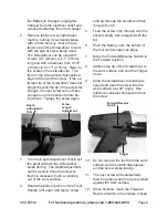
Remove the Screw Length Adjust

-

2. 

ment by turning it counterclockwise 

with a 3mm hex key.  Move the ex-

tension tip of the Screwdriver to work 

with the size of screw being used.  

The Screwdriver can be used with 

screws 0.9” (25mm) to 2.1” (55mm) 

long and with a diameter from 0.137” 

(3.5mm) to 0.177” (4.5mm).  Refer to 

the scale on the extended tip.  The 

front of the Screwdriver must extend 

beyond the tip of the screw.  If the ex-

tended tip of the screwdriver does not 

project beyond the tip of the screw far 

enough, the next screw will not have 

enough room to advance before be-

ing driven.  Tighten the screw again.

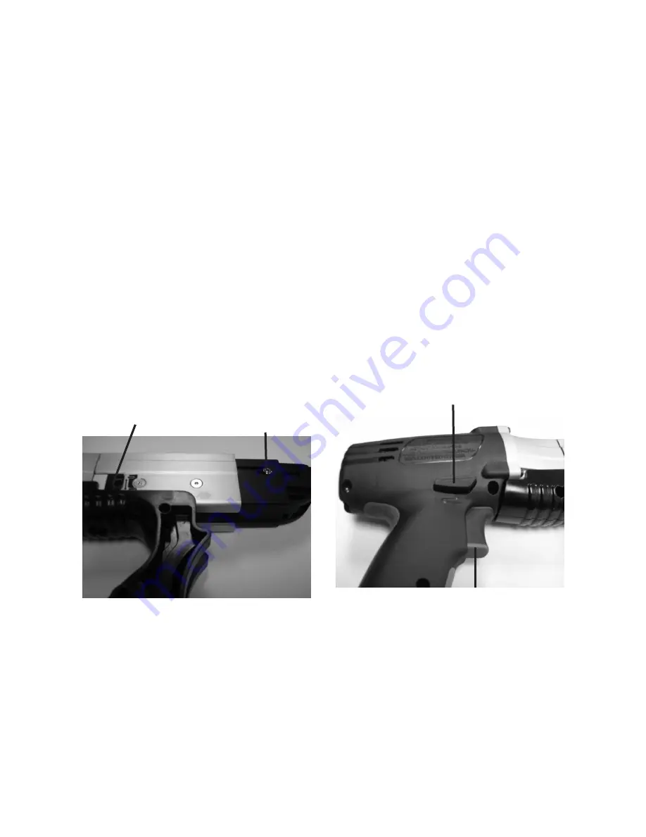
depth 

adjustment 

dial

screw 

length 

adjustment

3. 

Turn the Depth Adjustment Dial to set 

the point at which the Screwdriver 

stops driving.  The Depth Adjustment 

can be used to drive the screw so 

that it is recessed, flush, or sticking 

out of the work surface.   
Rotate the bottom portion of the Front 

4. 

Handle (25) down and feed a screw 

strip up through the handle and then 

through the tip.  
Feed the screw strip through until the 

5. 

second empty slot is aligned with the 

bit.
Push the Battery onto the bottom of 

6. 

the tool until it snaps into place.
Move the Forward/Reverse Switch to 

7. 

the Forward position.
Address the tip of the Screwdriver to 

8. 

the work surface and hold the Trigger 

down.  
Allow the Screwdriver to build up to 

9. 

speed and push the screw into the 

work surface at a 90° angle.  Use 

light but consistent pressure to drive 

the screw.

trigger

forward/reverse 

switch

10.  Do not remove the tool from the work 

surface until the clutch disengages 

and the screw stops turning. 
The next screw will automatically 

11. 

feed into place when the tip is pushed 

against the work surface.

When finished, move the Forward/

12. 

Reverse Switch to the middle, locked 

Summary of Contents for 99683

Page 1: ... manual Copyright 2008 by Harbor Freight Tools All rights reserved No portion of this manual or any artwork contained herein may be reproduced in any shape or form without the express written consent of Harbor Freight Tools Diagrams within this manual may not be drawn proportionally Due to continuing improvements actual product may differ slightly from the product described herein Tools required f...

Page 2: ... safety alert symbol indicates a hazardous situation which if not avoided could result in minor or moderate injury NOTICE is used to address practices not related to personal injury CAUTION without the safety alert symbol is used to address practices not related to personal injury General Power Tool Safety Warnings WARNING Read all safety warnings and instructions Failure to follow the warnings an...

Page 3: ...may result in serious personal injury Use personal protective equip b ment Always wear eye protection Safety equipment such as dust mask non skid safety shoes hard hat or hearing protection used for appropri ate conditions will reduce personal injuries Prevent unintentional starting c Ensure the switch is in the off po sition before connecting to power source and or battery pack pick ing up or car...

Page 4: ...ntended could result in a hazardous situation Battery tool use and care 5 Recharge only with the charger a specified by the manufacturer A charger that is suitable for one type of battery pack may create a risk of fire when used with another battery pack Use power tools only with specifi b cally designated battery packs Use of any other battery packs may create a risk of injury and fire When batte...

Page 5: ...isher and a smoke detector in the area Fre quently monitor the charger and battery during use This product is not a toy Keep it out 8 of reach of children People with pacemakers should 9 consult their physician s before use Electromagnetic fields in close prox imity to heart pacemaker could cause pacemaker interference or pacemak er failure In addition people with pacemakers should Avoid operating...

Page 6: ...ld first be examined by a doctor and then have regular medical check ups to ensure medical problems are not being caused or worsened from use Pregnant women or people who have impaired blood circulation to the hand past hand injuries ner vous system disorders diabetes or Raynaud s Disease should not use this tool If you feel any medical or physical symptoms related to vibra tion such as tingling n...

Page 7: ...ginning of this manual including all text under subheadings therein before set up or use of this product Work Piece and Work Area Set Up Designate a work area that is clean 1 and well lit The work area must not allow access by children or pets to prevent injury and distraction Secure loose work pieces using a 2 vise or clamps not included to pre vent movement while working There must not be hazard...

Page 8: ... set the point at which the Screwdriver stops driving The Depth Adjustment can be used to drive the screw so that it is recessed flush or sticking out of the work surface Rotate the bottom portion of the Front 4 Handle 25 down and feed a screw strip up through the handle and then through the tip Feed the screw strip through until the 5 second empty slot is aligned with the bit Push the Battery ont...

Page 9: ... To remove screws move the For 13 ward Reverse Switch to the Reverse position insert the bit into the head of the screw and squeeze the trigger until the screw is removed To prevent accidents move the For 14 ward Reverse switch to the middle locked position turn off the tool and disconnect its battery after use Clean then store the tool indoors out of children s reach ...

Page 10: ...d before further use Cleaning Maintenance and Lubrication BEFORE EACH USE 1 inspect the general condition of the tool Check for loose screws misalignment or binding of moving parts cracked or broken parts damaged electrical wir ing and any other condition that may affect its safe operation If the bit breaks or wears down it will 2 need to be changed Remove the hex bolt located in the center of the...

Page 11: ...r diagnosing or servicing the tool Disconnect power supply before service PLEASE READ THE FOLLOWING CAREFULLY The manufacturer and or distributor has provided the parts list and assembly diagram in this manual as a reference tool only Neither the manufacturer or distributor makes any representation or warranty of any kind to the buyer that he or she is qualified to make any repairs to the product ...

Page 12: ...1 12 Screw 7 13 Rear Grip 1 Parts List Part Description Qty 14 Front Grip 1 15 Battery 1 16 Battery Label 1 17 Battery Connection Assembly 1 18 Strap 1 19 Charger Lower Label 1 20 Charger 1 21 Charger Upper Label 1 22 Label 1 23 Screw 1 24 Washer 1 25 Front Handle 1 Record Product s Serial Number Here Note If product has no serial number record month and year of purchase instead Note Some parts ar...

Page 13: ...cidental or consequential damages so the above limitation of exclusion may not apply to you This warranty is express ly in lieu of all other warranties express or implied including the warranties of merchantability and fitness To take advantage of this warranty the product or part must be returned to us with transportation charges prepaid Proof of purchase date and an explanation of the com plaint...

Reviews: