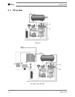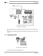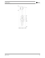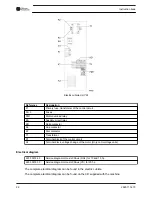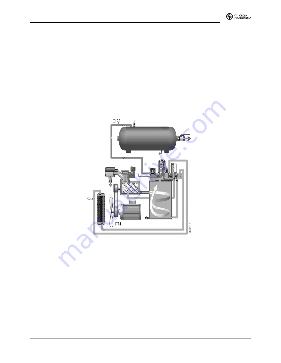
Air pressure in the oil separator tank (OT) forces the oil from the tank to compressor element (E)
via oil cooler (Co) and oil filter (OF). Compressed air and oil flow into oil separator/tank (OT)
where most of the oil is separated from the air by centrifugal action. The remaining oil is removed
by oil separator (OS) and returns to the oil circuit via a separate line. The minimum pressure
valve (Vp - see section
Air flow
) ensures a minimal pressure in the tank, required for oil
circulation under all circumstances.
The oil system is fitted with a by-pass valve (BV). When the oil temperature is below the set-point
of the valve, the by-pass valve shuts off the oil supply from oil cooler. The by-pass valve starts
opening the supply from cooler (Co) when the oil temperature exceeds the setting of the valve.
The setting of the by-pass valve depends on the model. See the section
Compressor data.
2.4
Cooling system
Cooling system
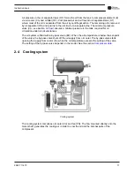
The cooling system comprises oil cooler (Co) and fan (FN). The fan, mounted directly onto the
motor shaft, generates the cooling air in order to cool the oil and the internal parts of the
compressor.
Instruction book
2920 7114 70
17
Summary of Contents for QRS 10
Page 2: ......
Page 18: ...2 3 Oil system Oil system Oil system units with dryer Instruction book 16 2920 7114 70 ...
Page 23: ...Electric cubicle UL DOL Instruction book 2920 7114 70 21 ...
Page 51: ...208 230 460V 60Hz Instruction book 2920 7114 70 49 ...
Page 74: ...8 Problem solving Control panel Air outlet valve Instruction book 72 2920 7114 70 ...
Page 75: ...Oil filler plug Condensate drain valve on air receiver Instruction book 2920 7114 70 73 ...
Page 84: ......
Page 85: ......
Page 86: ...No 2920 7114 70 2017 03 Printed in Belgium People Passion Performance www cp com ...


