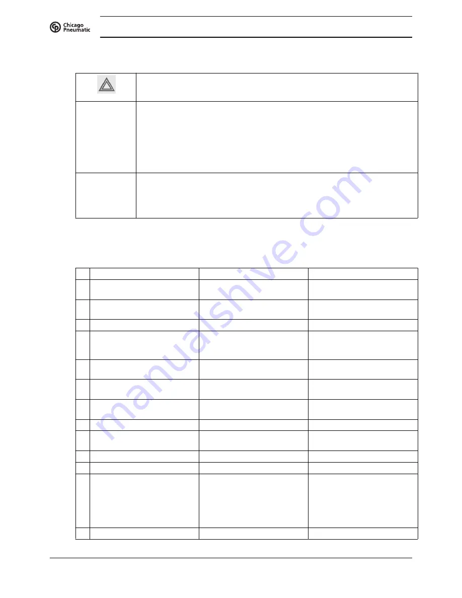
Attention
Use only authorised parts. Any damage or malfunction caused by the use of
unauthorised parts is not covered by Warranty or Product Liability.
Apply all relevant
Safety precautions during maintenance or repair
.
Before carrying out any maintenance or repair work on the compressor: push the stop
button (6).
Wait until the compressor has stopped and switch off the voltage. See the
Stopping
section.
Open the isolating switch to prevent an accidental start.
Close air outlet valve (2) and depressurise the compressor by opening the oil filler plug
(3) one turn.
Open manual condensate drain valves (4 and/or 5).
The air outlet valve (2) can be locked during maintenance or repair as follows:
• Close the valve.
• Remove the screw fixing the handle.
• Remove the handle.
• Fit the screw.
Faults and remedies
For all references given hereafter, see
Air flow diagram
,
Initial start-up
or
Regulating system
.
Condition
Fault
Remedy
1
Compressor starts running, but
does not load after a delay time
Solenoid valve (Y1) out of order
Replace valve
Inlet valve (IV) stuck in closed
position
Have valve checked
Leak in control air flexibles
Replace leaking flexible
Minimum pressure valve (Vp)
leaking (when net is
depressurised)
Have valve checked
2
Compressor air output or
pressure below normal
Air consumption exceeds air
output of compressor
Check equipment connected
Choked air inlet filter element
(AF)
Replace filter element
Solenoid valve (Y1)
malfunctioning
Replace valve
Leak in control air flexibles
Replace leaking flexible
Inlet valve (IV) does not fully
open
Have valve checked
Oil separator (OS) clogged
Replace separator element
Safety valves leaking
Replace valves
3
Air outlet temperature above
normal
Insufficient cooling air or cooling
air temperature too high
Check for cooling air restriction
or improve ventilation of
compressor room. Avoid
recirculation of cooling air. If
installed, check capacity of
compressor room fan
Oil level too low
Check and correct as necessary
Instruction book
74
2920 7114 70
Summary of Contents for QRS 10
Page 2: ......
Page 18: ...2 3 Oil system Oil system Oil system units with dryer Instruction book 16 2920 7114 70 ...
Page 23: ...Electric cubicle UL DOL Instruction book 2920 7114 70 21 ...
Page 51: ...208 230 460V 60Hz Instruction book 2920 7114 70 49 ...
Page 74: ...8 Problem solving Control panel Air outlet valve Instruction book 72 2920 7114 70 ...
Page 75: ...Oil filler plug Condensate drain valve on air receiver Instruction book 2920 7114 70 73 ...
Page 84: ......
Page 85: ......
Page 86: ...No 2920 7114 70 2017 03 Printed in Belgium People Passion Performance www cp com ...


